Programming_mail.pdf - 第48页
II- 4 Programming Manual Part II Inspection Data Step7: Enter Board Name of Destination to Save Inspection Data in Figure 1-3 and press Next . If User De fi ned in Step4 is checked, the format should be made newly. CAUTIO…
II-3
Programming Manual
Part II Inspection Data
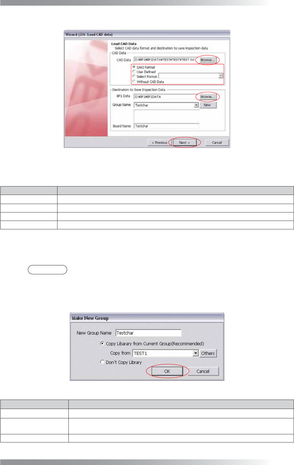
Step3: Press Browse in CAD Data to specify the CAD data.
Figure 1-3 Wizard 2
Step4: Select the format of the CAD data.
Item Description
SAKI Format
If a CAD data is output by Saki format, check
SAKI Format
.
User Defi ned
If a CAD data is output by another format, check User Defi ned.
Select Format
If a mount data is used, check Select Format.
Without CAD Data
If there is no CAD data, check Without CAD Data.
Table 1-1 Select the Format
Step5: Press Browse in BF1 Data to specify the
destination to save the inspection data.
NOTE
In the default setting, the inspection data is saved in D:\BF1\BF1DATA.
Step6: Select a group name from the Group Name drop-down list.
To add a new group, press New. The dialog shown in Figure 1-4 appears.
After all the settings are completed, press OK.
Figure 1-4 Make New Group
Item Description
New Group Name
Enter a new group name.
Copy Library from
Current Group
If using existing library data, check Copy Library from Current Group.
Select a library from the Copy from drop-down list.
Donʼt Copy Library If not using existing library data, check Donʼt Copy Library.
Table 1-2 Make New Group
II-4
Programming Manual
Part II Inspection Data
Step7: Enter Board Name of Destination to Save Inspection Data in Figure 1-3 and press Next. If User
Defi ned in Step4 is checked, the format should be made newly.
CAUTION
In case of a double-side PCB, both sides need each own user defi ne format.
NOTE
If SAKI Format or Select Format in Step4 is checked, CAD data will be automatically
extracted. Refer to after Step20 in Part II 1.1 Make Inspection data on AOI Machine.
NOTE
If Without CAD Data is checked, CAD data is not extracted. Make new inspection data
individually.
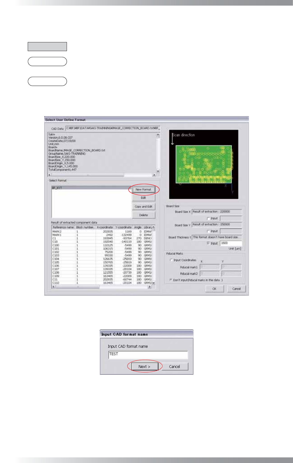
Step8: Press New Format to make a new format. If there is a similar format, press Copy and Edit.
Figure 1-5 User Defi ne Format
Step9: Enter a format name in the text-box and press Next.
Figure 1-6 Enter Format Name
II-5
Programming Manual
Part II Inspection Data
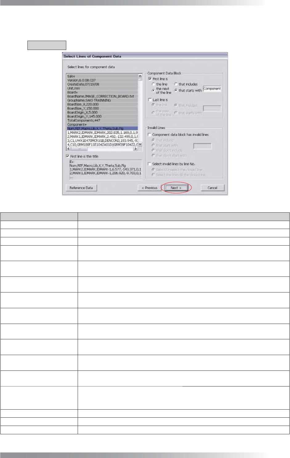
Step10: CAD data is displayed. Specify lines contain the component data such as names or coordinates of
components.
CAUTION
The text-box is case-sensitive.
Figure 1-7 Select Lines of Component Data
Item Description
First line is the title
If the fi rst line of component data defi ned each column, check First line is the title.
First line is
If specifying the fi rst line of component data, check First line is.
Last line is If specifying the last line of component data, check Last line is.
the line
and that includes
If specifying the line which is including words entered in the text-box, check the line
and that includes.
the next(prev.) of the line
and that includes
If specifying the next (previous) line of the line which is including words entered in
the text-box, check the next(prev.) of the line and that includes.
the line
and that starts with
If specifying the line that starts with the entered words in the text-box, check the
line and that starts with.
the next(prev.) of the line
and that starts with
If specifying the next (previous) line of the line that starts with the entered words in
the text-box, check the next(prev.) of the line and that starts with.
Component data block has
invalid lines
If component data have the line that does not include component information, check
Component data block has invalid lines. The specifi ed line becomes invalid line.
that include
If specifying the line which is including words entered in the text-box, check the line
and that includes.
that start with
If specifying the line that starts with the entered words in the text-box, check the
line and that starts with.
that don’t include
If specifying the line which is not including words entered in the text-box, check that
don’t include.
that don’t start with
If specifying the line that does not start with the entered words in the text-box,
check that don’t start with.
Select invalid lines by
line No.
If specifying the line that is not component data, check Select invalid lines by line
No.. As the particular line is specifi ed with this function, the user defi ne format
might be inapplicable to other CAD data.
Select/Unselect the clicked line
If specifying clicked line, check Select/Unselect the clicked line.
Select the lines till the clicked line
If specifying from the top line to the clicked line, check Select the lines till the clicked line.
Reference Data CAD data is displayed in another dialog.
Table 1-3 Description of Parameters