Programming_mail.pdf - 第226页
V- 36 Programming Manual Part V Other Function Step6: Press Fix Window after the adjustment of the area window is completed. CAUTION Area windows cannot be adjusted after pressing Fix Window . Figure 3-7 Fix Window Step7…
V-35
Programming Manual
Part V Other Function
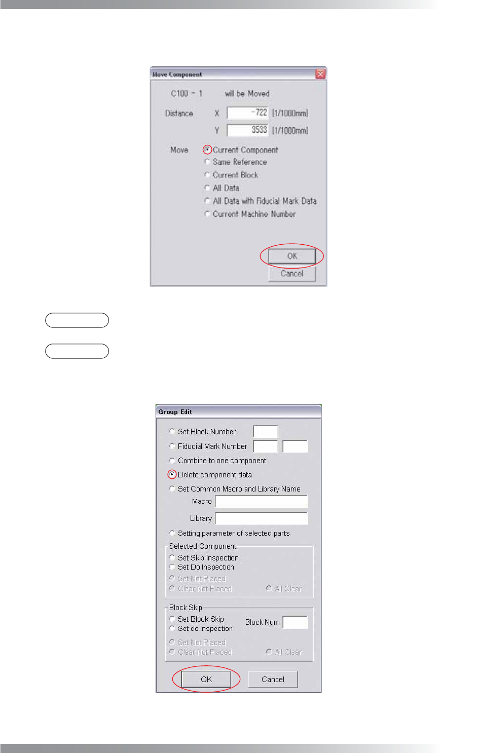
Step5: Drag the white window in the upper left side and the lower right side of area window. The dialog
shown in Figure 3-5 appears. Check Current Component and press OK.
Figure 3-5 Current Component
NOTE
Press Add in Figure 3-7 to add area window. Add Area window to the center of the screen.
NOTE
Drag the mouse to surround rectangles in the upper left side or the lower right side of area
window to delete area. The dialog shown in Figure 3-6 appears. Check Delete component
data and press OK.
Figure 3-6 Delete Component Data
V-36
Programming Manual
Part V Other Function
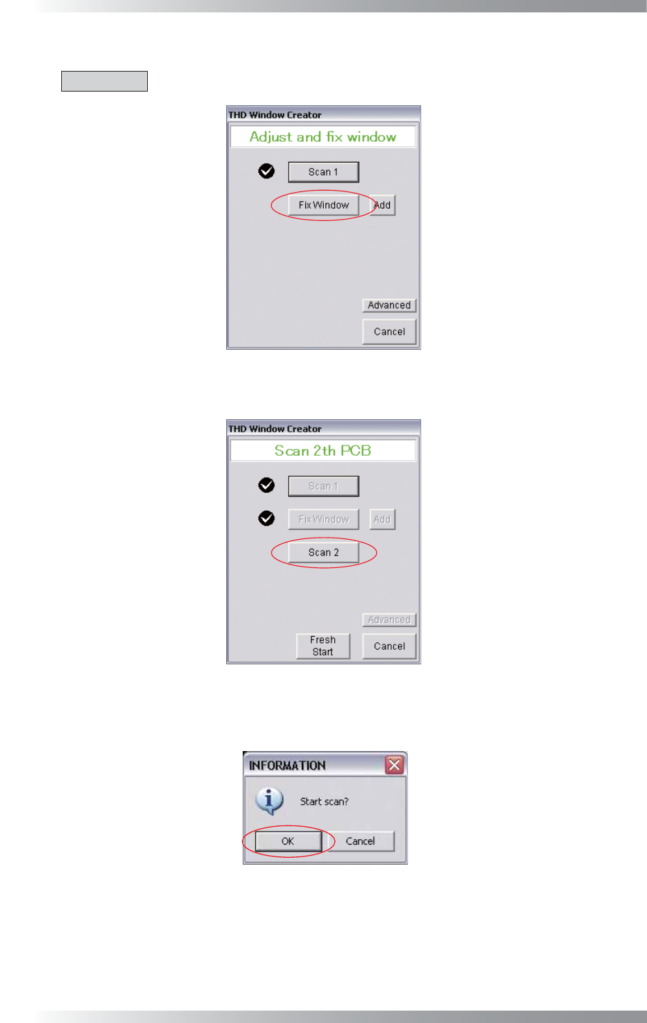
Step6: Press Fix Window after the adjustment of the area window is completed.
CAUTION
Area windows cannot be adjusted after pressing Fix Window.
Figure 3-7 Fix Window
Step7: Load the PCB and press Scan2.
Figure 3-8 Scan2
Step8: The dialog shown in Figure 3-9 appears. Press OK.
Figure 3-9 Start Scan
V-37
Programming Manual
Part V Other Function
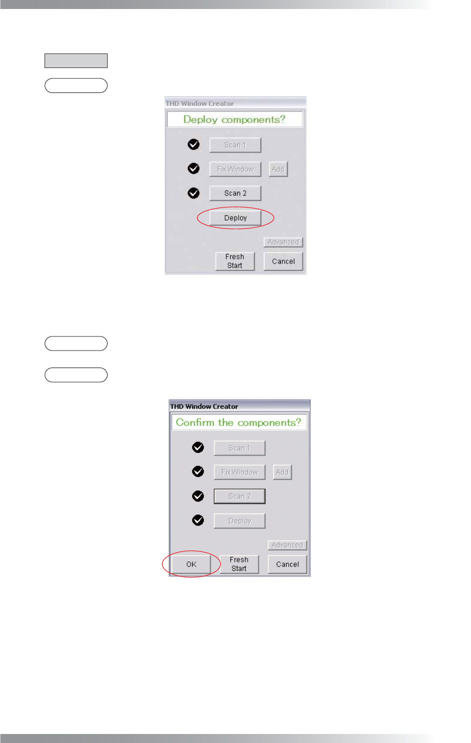
Step9: Press Deploy. The inspection data is automatically extracted.
CAUTION
Delete unnecessary inspection data.
NOTE
Images can be retaken by pressing Scan2 until Deploy is pressed.
Figure 3-10 Deploy
Step10: Press OK to confi rm the inspection data.
NOTE
If Fresh Start is pressed, the screen goes back to Step2 after deleting inspection data
without deleting area windows.
NOTE
If Cancel is pressed, THD Window Creator will close after deleting area windows and
inspection data.
Figure 3-11 Confi rm the component