Programming_mail.pdf - 第99页
III- 25 Programming Manual Part III Inspection Algorithm 1.9.7 Setting Procedur e of Av era ge (QFP) Step1: Refer to Step1 to 6 of Part III 1.9.6 Setting Procedure of Average (SOP) . Step2: Select the Average inspection …

III-24
Programming Manual
Part III Inspection Algorithm
1.9.6 Setting Procedure of Average (SOP)
Step1: Select a lighting that displays a polarity visually clear from the Lighting drop-down list.
Step2: Change the algorithm of Polarity to Average.
Step3: If the polarity mark is circle, change the inspection window shape to circle. Press Option in the
right side of Algorithm. Check Use non-rectangle window and Circle Window and press OK.
Step4: Adjust inspection window size to match with a polarity mark.
CAUTION
Change the lighting if there is no difference between polarity and component body
with default lighting.
Step5: Enter 255 in the Upper fi eld, 0 in the Lower fi eld, and M1 in the Memorize to fi eld.
Step6: Enter the appropriate vector into the Shift fi eld by selecting from V1 to V8 according to the
vector used in the Memorize to fi eld in the Adjust window.
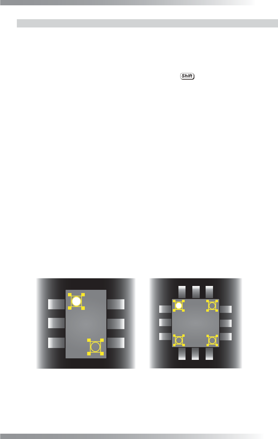
Step7: Select the Average inspection window. Right-click and select Point-Symmetric Copy.
Step8: Enter M2 in the Memorize to fi eld of the inspection window which is made on Step7.
Step9: Select the inspection window which is made on Step7. Right-click and select Copy Window.
Step10: Change the algorithm of the inspection window which is made on Step9 to Mem1-Mem2.
Step11: If brightness level of a polarity mark is higher than brightness level of the component body,
enter 255 in the Upper fi eld and 1 in the Lower fi eld. If brightness level of a polarity mark is
lower than brightness level of the component body, enter -1 in the Upper fi eld and -255 in
the Lower fi eld.
Step12: Enter M1 in the Memory1 fi eld and M2 in the Memory2 fi eld.
Step13: Press Inspect. Make sure that the inspection is completed properly.
III-25
Programming Manual
Part III Inspection Algorithm
1.9.7 Setting Procedure of Average (QFP)
Step1: Refer to Step1 to 6 of Part III 1.9.6 Setting Procedure of Average (SOP).
Step2: Select the Average inspection window. Right-click and select X-Symmetric Copy.
Step3: Select two Average inspection windows by pressing
.
Right-click and select Y-Symmetric Copy.
Step4: Change the Memorize to value of the Average inspection windows. Enter M2, M3, or M4
in the Memorize to fi eld of the inspection windows which are made in Step2 and Step3.
Step5: Select the inspection windows which are made in Step2 and Step3.
Right-click and select Copy Window.
Step6: Change the algorithm of the inspection windows which are made in Step5 to Mem1-Mem2.
Step7: Select the inspection windows which are made in Step5. Right-click and select Copy Window.
Repeat the same procedure twice to make two windows.
Step8: Change the Memory2 value of the Mem1-Mem2 inspection window. Enter M2, M3, or M4
in the Memory2 fi elds of the inspection windows which are made on Step7.
Step9: Change the Upper fi eld and Lower fi eld of Mem1-Mem2. If brightness level of a polarity
mark is higher than brightness level of the component body, enter 255 in the Upper fi eld
and 1 in the Lower fi eld. If brightness level of a polarity mark is lower than brightness level
of the component body, enter -1 in the Upper fi eld and -255 in the Lower fi eld.
Step10: Press Inspect. Make sure that the inspection is completed properly.
㪤㪈
㪤㪉
㪤㪈
㪤㪉
㪤㪊
㪤㪋
㩿㪸㪀㪪㪦㪧㩷 㩿㪹㪀㪨㪝㪧㩷
Figure 1-28 Inspection Window for Polarity Inspection
III-26
Programming Manual
Part III Inspection Algorithm
1.10 Diagonally
1.10.1 Inspection Overview
Diagonally is the algorithm to inspect the average luminance of the inspection windows which are
located on symmetrical positions from the center of component.
Diagonally is suitable for polarity inspection of IC components.
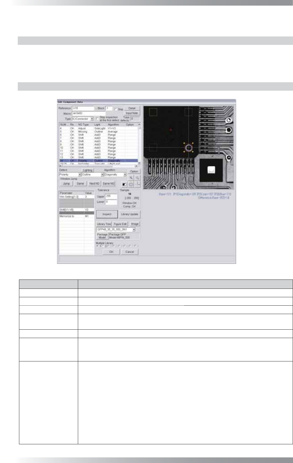
1.10.2 Parameter Setting
Figure 1-29 Diagonally
Parameter Description
Lighting Select a lighting that displays a polarity visually clear.
Algorithm Select Diagonally.
Win Setting[1-3] Set the number of the windows to be compared.
Shift[V1-V8]
Enter the appropriate vector. Any value from V1 to V8 is available.
Select the vector according to the Memorize to fi eld of the Adjust window.
Memorize to -
Upper, Lower
If brightness level of polarity is higher than brightness level of component body, enter 255
in the Upper fi eld and 1 in the Lower fi eld. If brightness level of polarity is lower than
brightness level of component body, enter -1 in the Upper fi eld and -255 in the Lower fi eld.
Sample
If 1 is entered in Win setting, the brightness level difference between the window
and the window on the point-symmetric point will be calculated and its result
becomes the sample value.
If 2 is entered, in addition to operations of 1, the brightness level difference between
the window and the window at the center point on the component will also be
calculated. Two brightness level difference values are compared and the bigger one
becomes the sample value.
If 3 is entered, in addition to operations of 1, the brightness level difference between
the window which the setting is applied and the window on the line-symmetric point
will be calculated. Three brightness level difference values are compared and the
biggest one becomes the sample value.
Table 1-8 Parameter of Diagonally