Programming_mail.pdf - 第213页
V- 23 Programming Manual Part V Other Function Step7: If Auto setting with inspection sensitive and free memory size in Step6 is checked, the dialog shown in Figure 2-9 appears. After all the settings are completed, pres…
V-22
Programming Manual
Part V Other Function
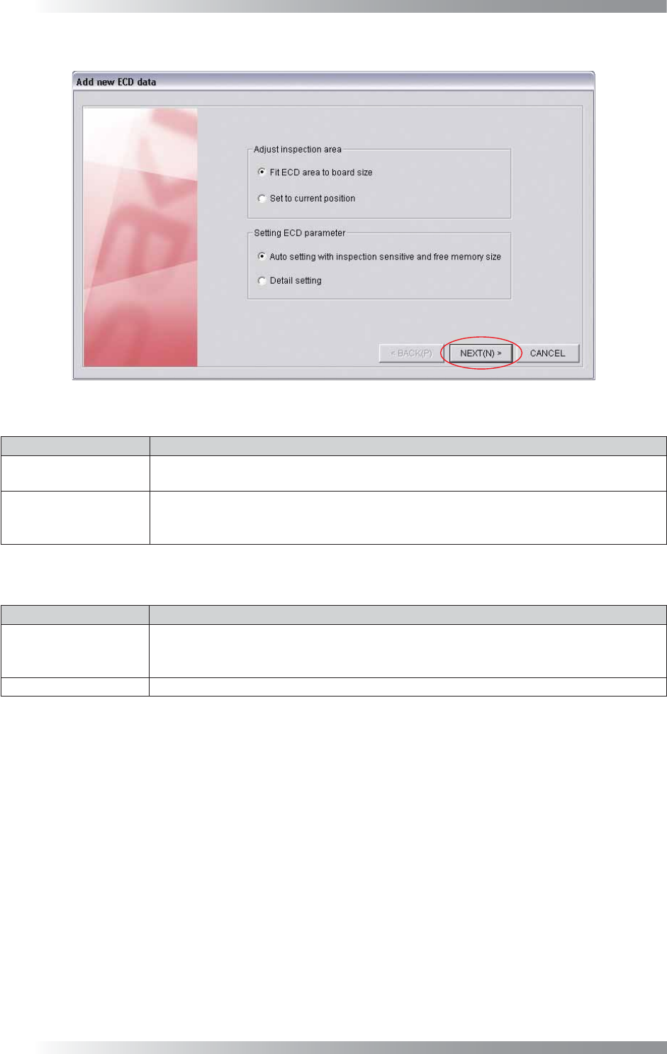
Step6: The dialog shown in Figure 2-8 appears. Check item, if necessary. Press NEXT.
Figure 2-8 Add New ECD Data
Item Description
Fit ECD area
to board size
Automatically extracts the ECD inspection window to fi t the PCB size.
Set to current position
Extracts the ECD inspection window on the white cross line displayed by left-clicking the
mouse. This item is used when changing the inspection window size or setting multiple
ECD inspection windows on the PCB.
Table 2-3 Adjust Inspection Area
Item Description
Auto setting with
inspection sensitive
and free memory size
Set a parameter automatically.
Select the inspection level from LOW, MIDDLE, HIGH depending on the inspection accuracy.
Detail setting Set a parameter manually.
Table 2-4 Setting ECD Parameter
V-23
Programming Manual
Part V Other Function
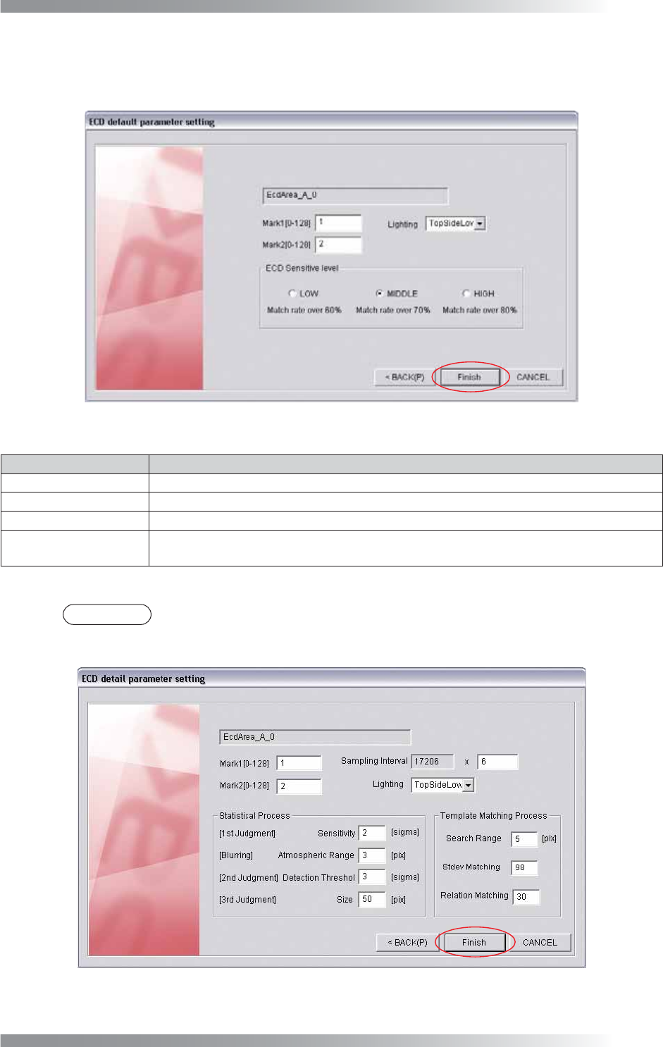
Step7: If Auto setting with inspection sensitive and free memory size in Step6 is checked, the dialog
shown in Figure 2-9 appears. After all the settings are completed, press Finish. ECD inspection
window will be extracted according to settings of Table 2-3 Adjust Inspection Area.
Figure 2-9 ECD Default Parameter Setting 1
Item Description
Mark1 [0-128] Enter 1.
Mark2 [0-128] Enter 2.
Lighting Select TopSideLow.
ECD Sensitive level
Select the inspection level from LOW, MIDDLE, HIGH depends on the inspection accuracy.
Match rate shows matching rate of the images of inspection PCB and template.
Table 2-5 ECD Default Parameter Setting 1
NOTE
If Detail setting in Step6 is checked, the dialog shown in Figure 2-10 appears. Refer to
Table 2-8 to set parameters manually. Press Finish.
Figure 2-10 ECD Default Parameter Setting 2
V-24
Programming Manual
Part V Other Function
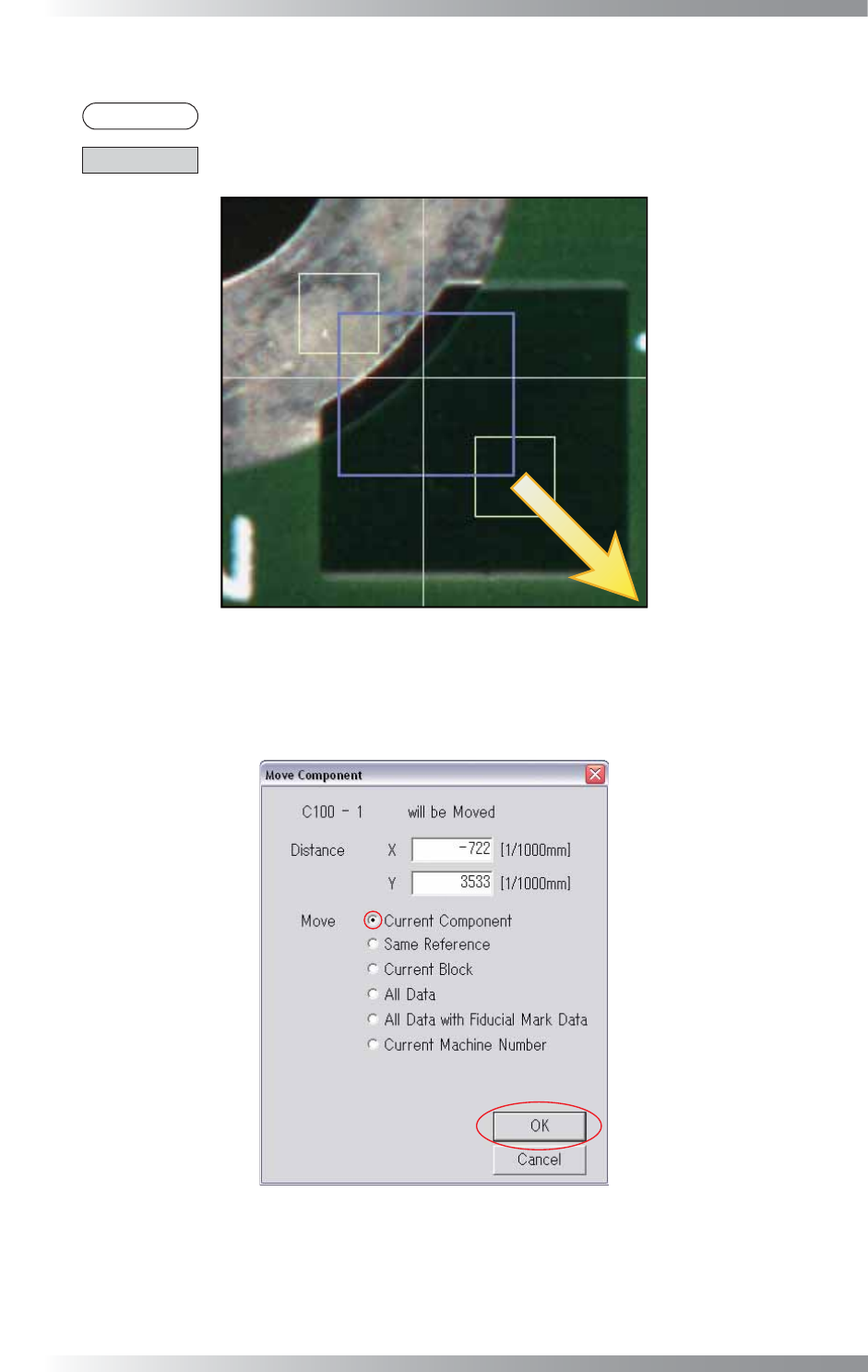
Step8: Yellow and purple windows are displayed. Drag the yellow window to adjust inspection area.
NOTE
Purple window shows inspection area.
CAUTION
Be sure to set an inspection area inside of fi ducial marks.
Figure 2-11 Enlarge Inspection Area
Step9: After dragging the yellow window, the dialog shown in Figure 2-12 appears.
Check Current Component and press OK.
Figure 2-12 Move Component Data