Programming_mail.pdf - 第70页
II- 26 Programming Manual Part II Inspection Data 1.3 Auto Deplo yment of Inspection Data If a component does not have a corresponding library , inspection data needs to be made individually . Use the auto deployment of …
II-25
Programming Manual
Part II Inspection Data
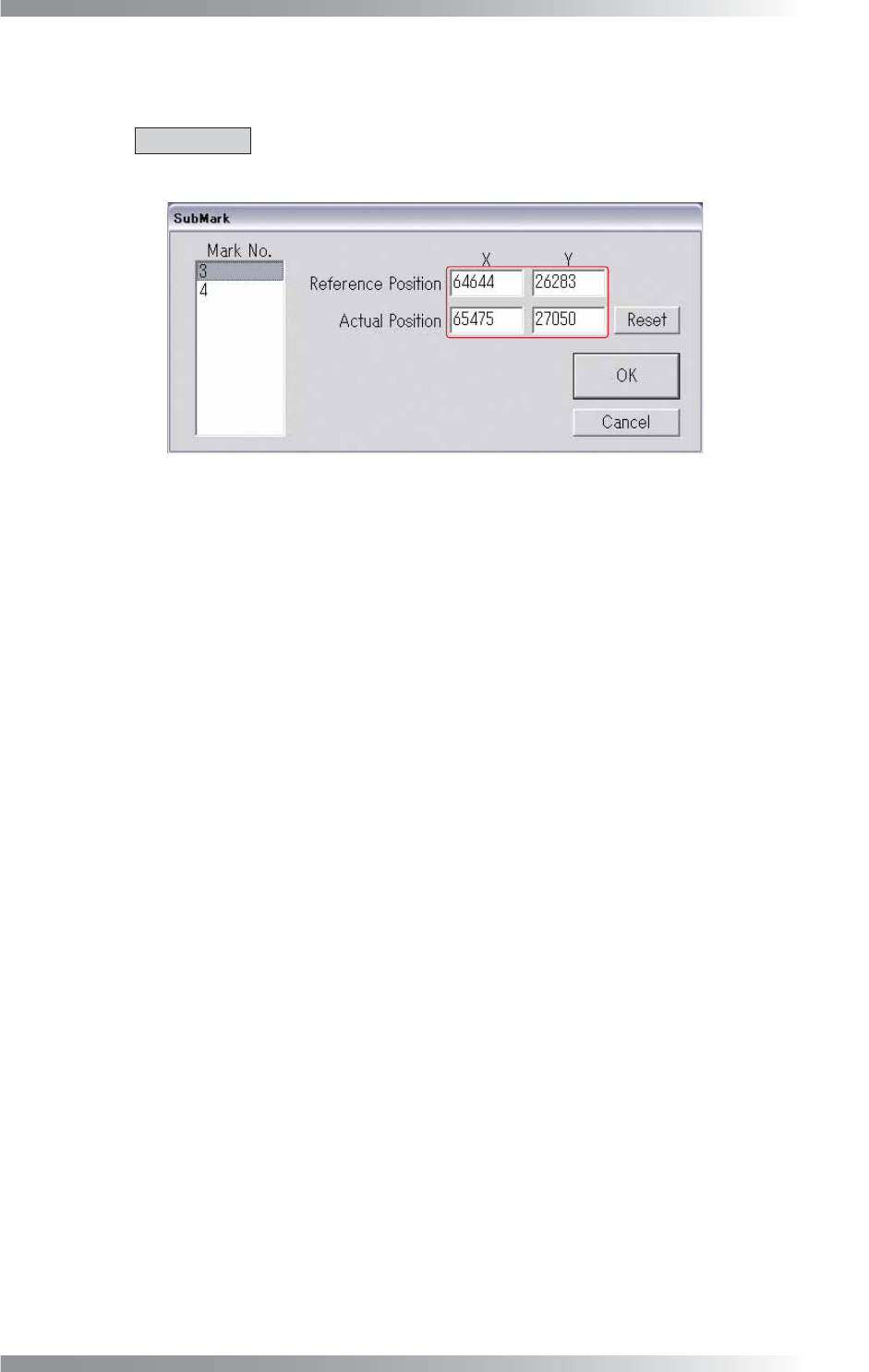
Step9: The dialog shown in Figure 1-46 appears.
Make sure that coordinates are entered correctly.
CAUTION
If 0 or 999999 are entered as coordinates, press Reset to reset the sub mark.
Press OK.
Figure 1-46 Sub Mark Edit
II-26
Programming Manual
Part II Inspection Data
1.3 Auto Deployment of Inspection Data
If a component does not have a corresponding library, inspection data needs to be made individually.
Use the auto deployment of inspection data to make inspection data easily.
The auto deployment procedure differs between chip components and IC components.
1.3.1 Auto Deployment of Chip Component
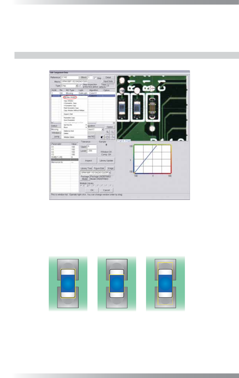
Step1: Right-click the center of CAD data. The dialog shown in Figure 1-47 appears.
Figure 1-47 Auto Deployment of Chip Component 1
Step2: Select Add New Window from the right-click menu and repeat it three times to make three
inspection windows. Adjust the fi rst inspection window size to surround an electrode and
body of a component. Adjust the second inspection window size to surround a body of a
component. Adjust the third inspection window size to surround a pad, electrode, and body
of a component.
(1) Electrode and Body (2) Body (3) Pad, Electrode, and Body
Figure 1-48 Auto Deployment of Chip Component 2
II-27
Programming Manual
Part II Inspection Data
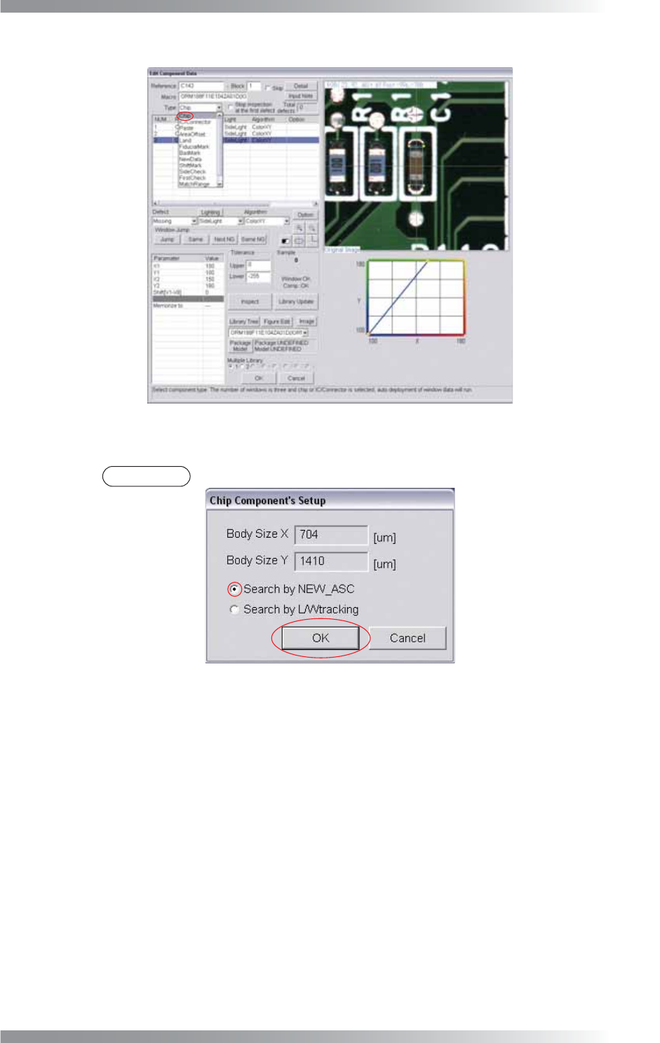
Step3: Select Chip from the Type drop-down list.
Figure 1-49 Auto Deployment of Chip Component 3
Step4: Check Search by NEW_ASC and press OK.
NOTE
If electrodes of a chip component are not visually clear, check Search by L/Wtracking.
Figure 1-50 Auto Deployment of Chip Component 4
Step5: Inspection items are automatically made. For details of inspection data settings, refer to
Part III Inspection Algorithm.