Programming_mail.pdf - 第234页
V- 44 Programming Manual Part V Inspection Data 4.4 Pin Hole Inspection Setting Pin hole inspection detects the hole in the solder . 4.4.1 Parameter of Copper Inspection Figure 4-7 Pin Hole Inspection Setting Parameter D…
V-43
Programming Manual
Part V Inspection Data
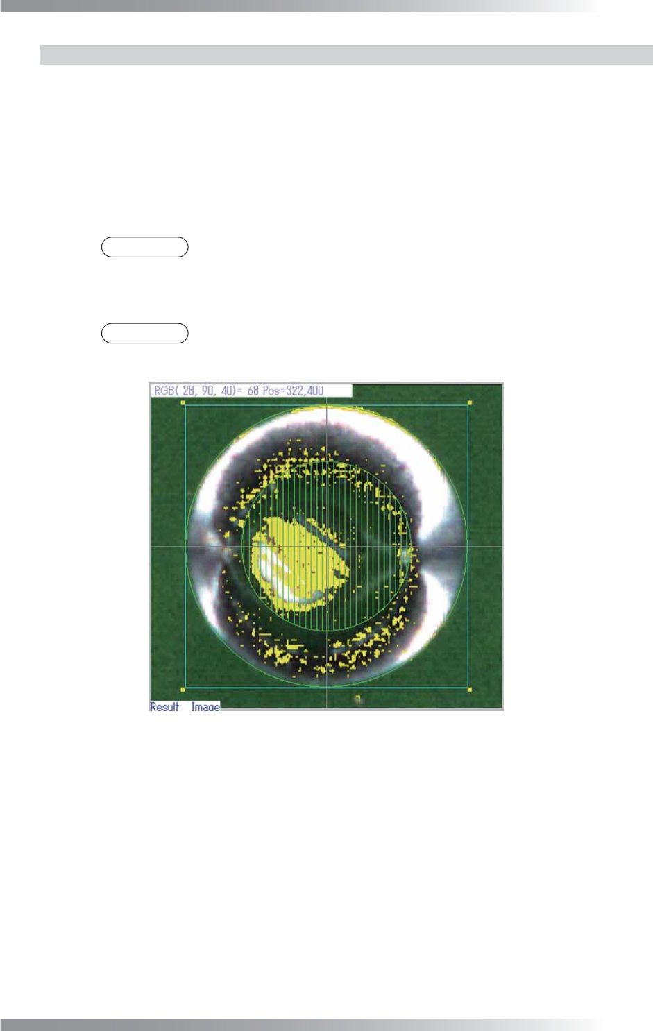
4.3.2 Setting Procedure of Copper Inspection
Step1: Press COPPER button.
Step2: Check Inspect Copper.
Step3: Adjust Width to surround the pad. The inspection area is specifi ed by width (pixel value)
from the green circle. The inspection area is in the green circle except the area netted. Enter
the bigger value to enlarge the inspection area.
NOTE
To set the netted area to pin hole inspection area, check Link area size of Copper
and PinHole.
Step4: Enter a value in Upper limit fi eld.
NOTE
Detected shows the percentage of the copper area as the yellow line in the
inspection area.
Figure 4-6 Copper inspection
V-44
Programming Manual
Part V Inspection Data
4.4 Pin Hole Inspection Setting
Pin hole inspection detects the hole in the solder.
4.4.1 Parameter of Copper Inspection
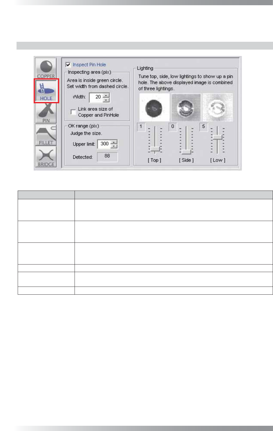
Figure 4-7 Pin Hole Inspection Setting
Parameter Description
Inspect Pin Hole
To activate Pin hole inspection, check Inspect Pin Hole .
To disable pin hole inspection, un-check Inspect Pin Hole.
Buttonʼs color is displayed as gray.
Width
The inspection area is specifi ed by width (pixel value) from the dotted line circle.
The inspection area is in the green circle.
Enter the smaller value to enlarge the inspection area.
Link area size of
Copper and PinHole
The inspection area size of Copper and Pin Hole are interlocked.
Width of Copper and Width of Pin Hole become same value. The inspection area
indicated by netting on the window of Copper becomes the inspection area of Pin Hole.
Upper limit Set the upper limit of the OK range.
Detected
Detects holes in a solder fi llet. After inspecting, the number of pixels of a hole (an area
whose color is recognized as black) is displayed above a Pin hole inspection window.
Lighting
Adjusts the each lighting slider to display the hole as the black.
Table 4-4 Parameter of Pin Hole Inspection
V-45
Programming Manual
Part V Inspection Data
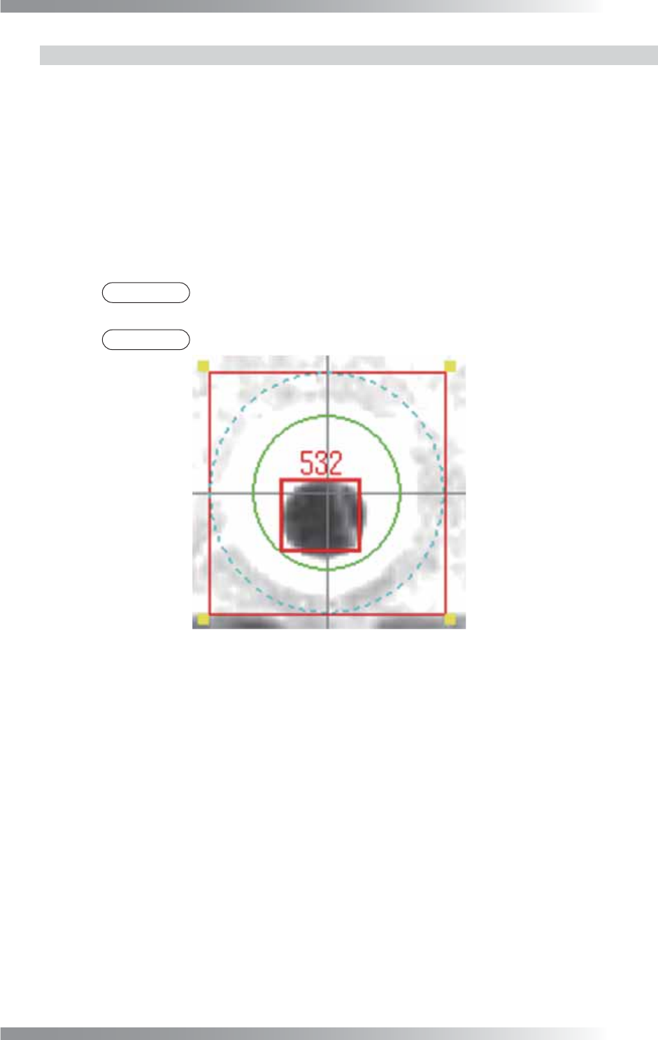
4.4.2 Setting Procedure of Pin Hole Inspection
Step1: Press HOLE button.
Step2: Check Inspect Pin Hole.
Step3: Adjust Width to surround the hole. The inspection area is specifi ed by width (pixel value)
from the green circle. The inspection area is in the green circle. Enter the bigger value to
enlarge the inspection area.
Step4: Enter a value in the Upper limit fi eld.
NOTE
Detected indicates the number of pixels of the hole (an area whose color is
recognized as black).
NOTE
The value displayed on the screen indicates the value of Detected.
Figure 4-8 Pin Hole Inspection