Programming_mail.pdf - 第32页
I- 24 Programming Manual Part I Basic Operation 2.5.2 Setting by Type of Mar king Here describes the way to setup marking respectively . Step1: Open the inspection data to change the marking setting. Step2: Select Edit &…
I-23
Programming Manual
Part I Basic Operation
2.3 ALC
This section describes the setting of Automatic Luminance Control.
All parameter is adjusted appropriately at the time of installation or before shipping.
CAUTION
Normally customers do not need to modify the Automatic Luminance Control setting as
wrong setting cause unexpected errors.
2.4 Motor
This section describes settings of Motors.
All parameter is adjusted appropriately at the time of installation or before shipping.
CAUTION
Normally customers do not need to modify the Automatic Luminance Control setting as
wrong setting cause unexpected errors.
2.5 Marking
This section describes how to set the marking function.
Collective Setting and Setting by Type of Marking are available to set the marking function.
If both are selected, Setting by Type of Marking will be used.
CAUTION
This function is available only on models with marking units.
2.5.1 Collective Setting
Press Marking in Figure 2-1 Select System Setup.
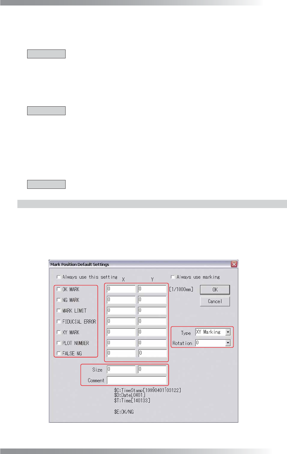
The Mark Position Default Settings dialog shown in Figure 2-5 appears.
A in Figure 2-5 specifi es a type of a marking. B specifi es a position of a marking. C specifi es a plot
selection of an XY marking and a rotation angle of characters by PLOT NUMBER when plotting.
D specifi es a size of characters and a content of a comment (in the case of selecting PLOT NUMBER).
A
B
D
C
Figure 2-5 Mark Position Default Settings
I-24
Programming Manual
Part I Basic Operation
2.5.2 Setting by Type of Marking
Here describes the way to setup marking respectively.
Step1: Open the inspection data to change the marking setting.
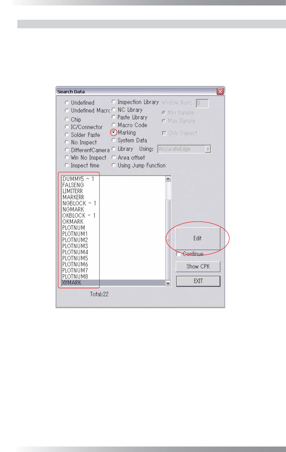
Step2: Select Edit > Search from the menu-bar.
The Search Data dialog shown in Figure 2-6 appears.
Figure 2-6 Search Data
I-25
Programming Manual
Part I Basic Operation
XY Marking (Painting) Setup
Check Marking in Figure 2-6 Search Data, select XYMARK and press Edit. The XY Painting Setup
dialog shown in Figure 2-7 appears. Refer to Table 2-4 XY Painting Setup and proceed the setup
procedures. After all the settings are completed, press OK.
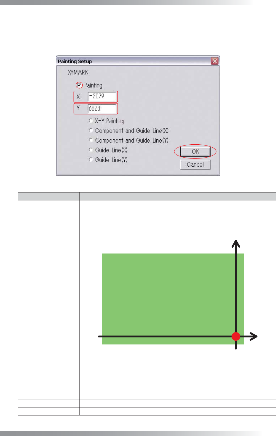
Figure 2-7 XY Painting Setup
Item
Description
Painting
When checked, the XY painting (marking) function works.
XY Coordinates Setup
The marking positions for NG components can be specifi ed.
“X,Y = (325000, 5000) [μm]” is set as the marking origin (X,Y = (0, 0) [μm]) as
shown in Figure 2-8. If changing marking positions, enter coordinates from this
origin point.
Figure 2-8 XY Coordinates Setup
X-Y Painting
Puts marks on the specifi ed coordinates point.
Component and
Guide Line (X)
Puts two marks, one on the NG components, and the other on the axis of X
coordinates of the component.
Component and
Guide Line (Y)
Puts two marks, one on the NG components, and the other on the axis of Y
coordinates of the component.
Guide Line (X) Puts a mark on the axis of X coordinates of the NG component.
Guide Line (Y)
Puts a mark on the axis of Y coordinates of the NG component.
Table 2-4 XY Painting Setup