Programming_mail.pdf - 第121页
III- 47 Programming Manual Part III Inspection Algorithm Step15: If changing a number of leads, press Detail shown in Figure 1-55. The dialog shown in Figure 1-56 appears. Figure 1-55 Detail Figure 1-56 Number of Electro…
III-46
Programming Manual
Part III Inspection Algorithm
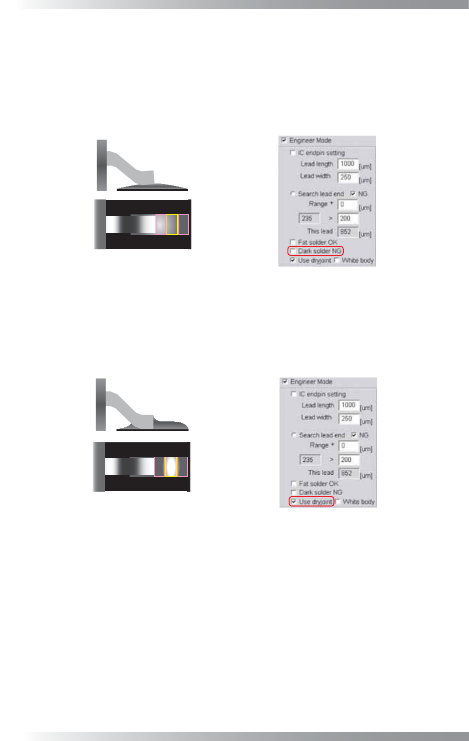
Step12: If solder volume is extremely low, the solder brightness level in pad end area is darker than
pad center area. Check Dark solder NG if necessary. The inspection is done as following
steps, lead shift, lead bend, no solder, copper exposure, and lifted lead. If Dark solder NG
is checked, lifted lead inspection will be changed. After copper exposure inspection, the
average brightness level in pad lead, pad center, and pad end area is calculated. If the
sample value is lower than 100, the result will be NG. In this case, the lifted lead inspection
will be skipped.
Dark Solder
Figure 1-53 Dark solder NG
Step13: In case of dry joint, the brightness level in pad center area is brighter than pad lead and pad
end area. Check Use dryjoint if necessary. If Use dryjoint is checked and either of the
brightness level in pad end area minus pad center area or the brightness level in pad
end area minus pad lead area is failed, the result will be NG. In this case, the third
inspection, the brightness level in pad center area minus pad lead area, is skipped.
Dryjoint
Figure 1-54 Use dryjoint
Step14: Check White body in case the body is brighter than leads (e.g., Connectors).

III-47
Programming Manual
Part III Inspection Algorithm
Step15: If changing a number of leads, press Detail shown in Figure 1-55. The dialog shown in
Figure 1-56 appears.
Figure 1-55 Detail
Figure 1-56 Number of Electrodes
Step16: Enter the number of leads in Number of Electrodes and press OK.
Step17: Enter the appropriate vector into the Shift fi eld. Any value from V1 to V8 is available.
Select the vector according to the Memorize to fi eld of the Adjust window.
Step18: Press Inspect. Make sure that the inspection is completed properly.
III-48
Programming Manual
Part III Inspection Algorithm
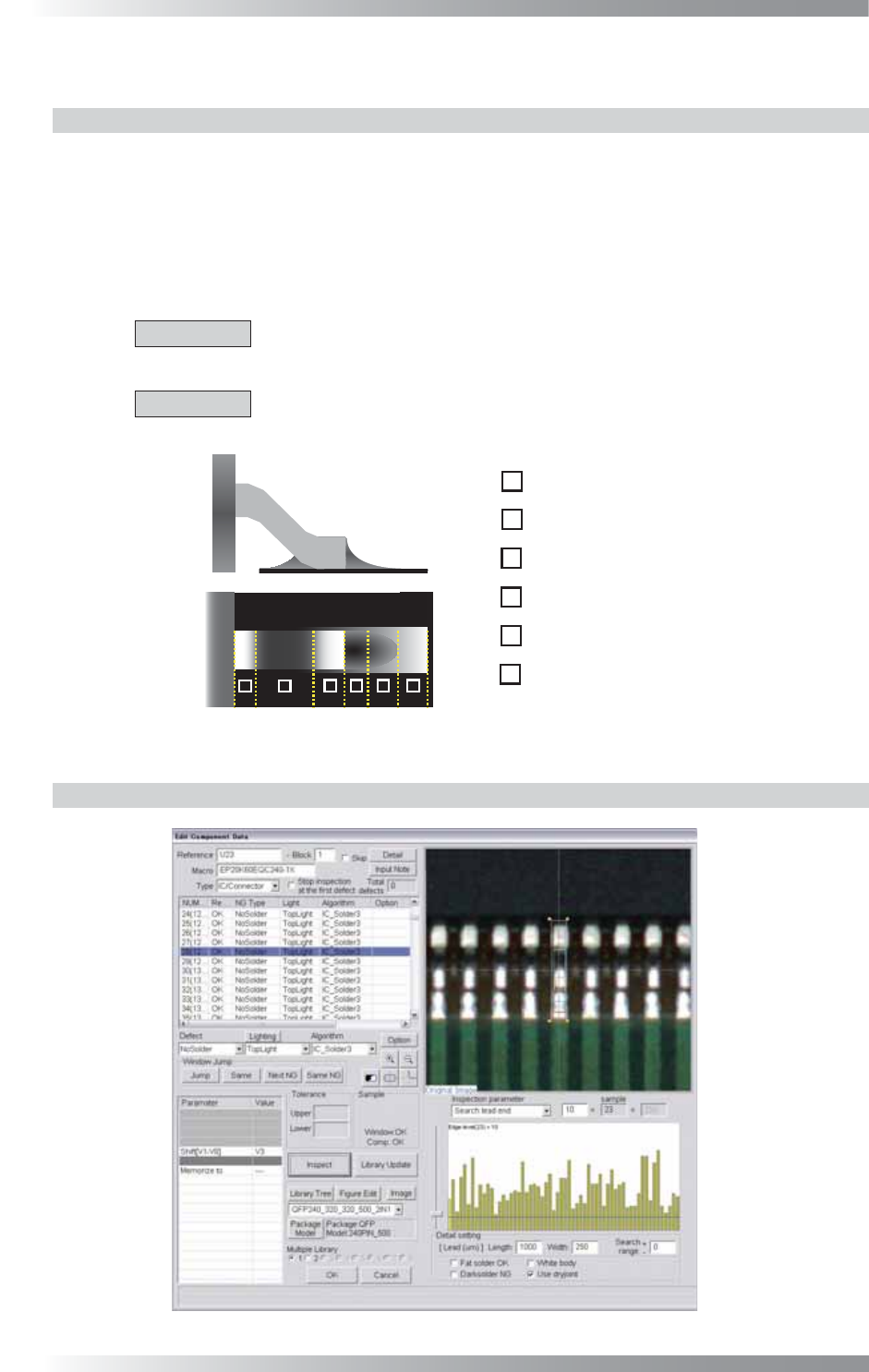
1.14 IC_Solder3
1.14.1 Inspection Overview
IC_Solder3 is the algorithm to inspect the lead length, shift, bend, solder conditions, and lifted lead
in only one inspection window with high accuracy.
Operability has been improved from the conventional IC_Solder2 algorithm and now lead bend can
be inspected.
It automatically locates inspection points (lead end, lead base, pad end) of an IC component.
The algorithm inspects a lead length, lead shift, lead bend, solder, copper and lifted lead in order.
CAUTION
If lead length or lead shift inspection is NG, all the following inspections, solder,
copper and lifted lead inspections are skipped.
CAUTION
IC_Solder3 is not available for two lighting system machine. It is also not valid in
combination with Part III 1.22 AS_Av_LeadLength.
㪈
㪉
㪊
㪋
㪌
㪍
㪈
㪉
㪊
㪋
㪌
㪍
Lead Base Area
Gull Wing Area
Lead End Area
Pad Lead Area
Pad Center Area
Pad End Area
Figure 1-57 Inspection of IC_Solder3
1.14.2 Parameter Setting
Figure 1-58 IC_Solder3