Programming_mail.pdf - 第241页
V- 51 Programming Manual Part V Inspection Data 4.7.2 Setting Procedur e of Fillet Inspection Step1: Press FILLET button. Step2: Check Inspect Fillet . Step3: Enter values into the Upper limit and Lower limit fi eld. NOTE…
V-50
Programming Manual
Part V Inspection Data
4.7 Fillet Inspection Setting
In Fillet Inspection, defections of fat solder and no solders can be detected from a fi llet shape.
CAUTION
Fillet Inspection can be used if straight pin is selected in the pin inspection.
This algorithm cannot be used when a clinch pin is selected or the pin inspection is set to off.
4.7.1 Parameter of Fillet Inspection
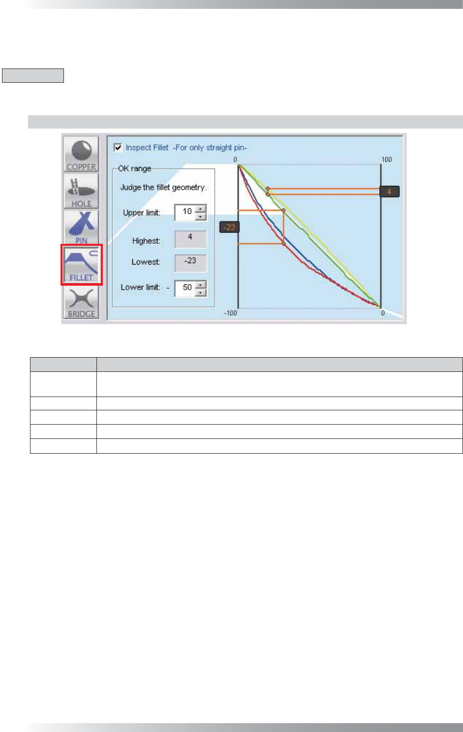
Figure 4-14 Fillet Inspection Setting
Parameter Description
Inspect Fillet
To activate Fillet inspection, check Inspect Fillet.
To disable Pin inspection, un-check Inspect Fillet. Buttonʼs color is displayed as gray.
Upper limit
Set the upper limit of an acceptable range.
Highest
Shows the distance between the base line (the white line) and top of a raised fi llet.
Lowest Shows the distance between the base line (the white line) and bottom of a sunken fi llet.
Lower limit
Set the lower limit of an acceptable range.
Table 4-7 Parameter of Fillet Inspection
V-51
Programming Manual
Part V Inspection Data
4.7.2 Setting Procedure of Fillet Inspection
Step1: Press FILLET button.
Step2: Check Inspect Fillet.
Step3: Enter values into the Upper limit and Lower limit fi eld.
NOTE
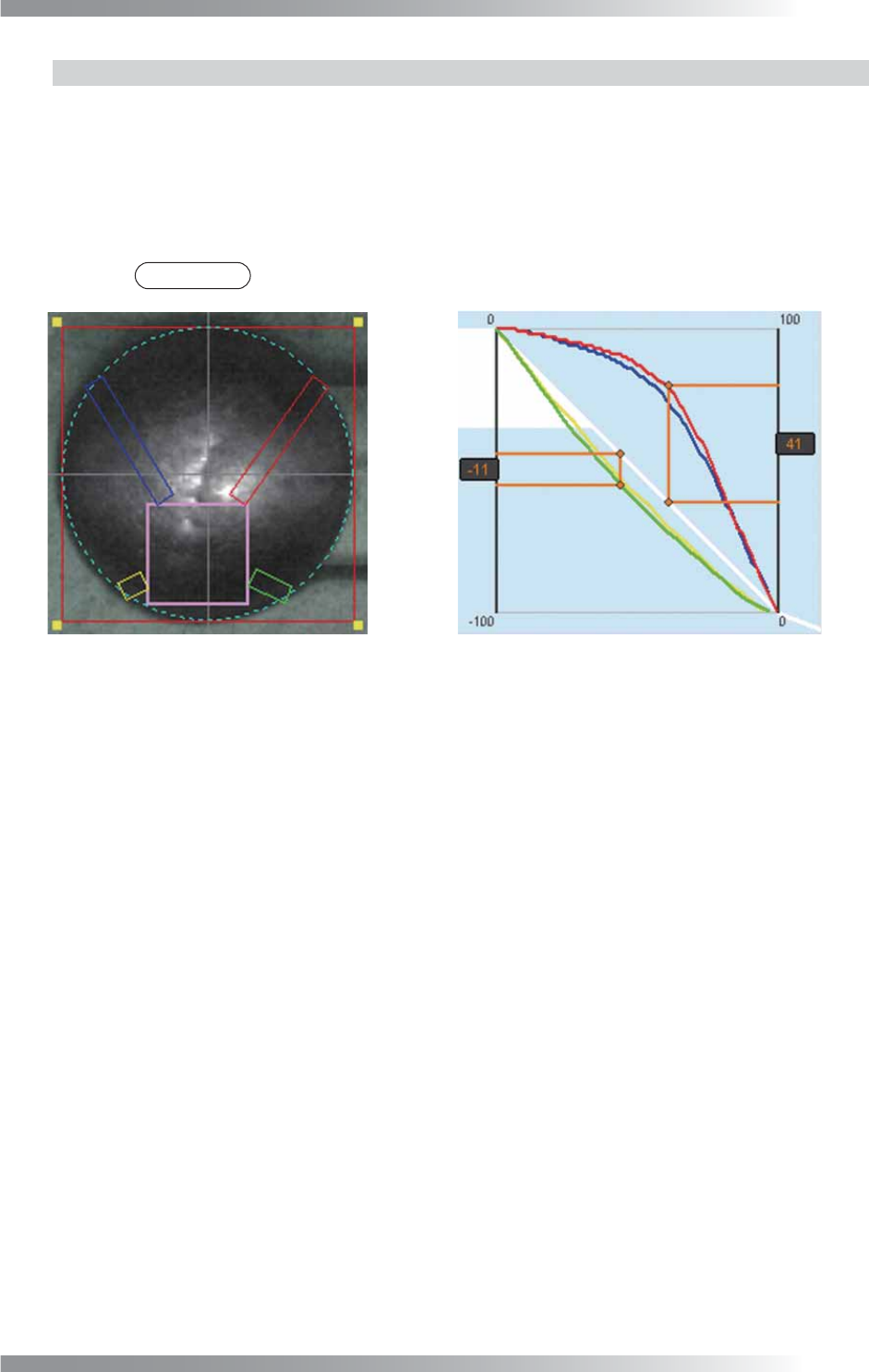
The color of the inspection window corresponds to the color of the graph.
Figure 4-15 Example of a raised fi llet
V-52
Programming Manual
Part V Inspection Data
4.8 Bridge Inspection Setting
Bridge inspection detects the solder bridge between pads.
4.8.1 Parameter of Bridge Inspection
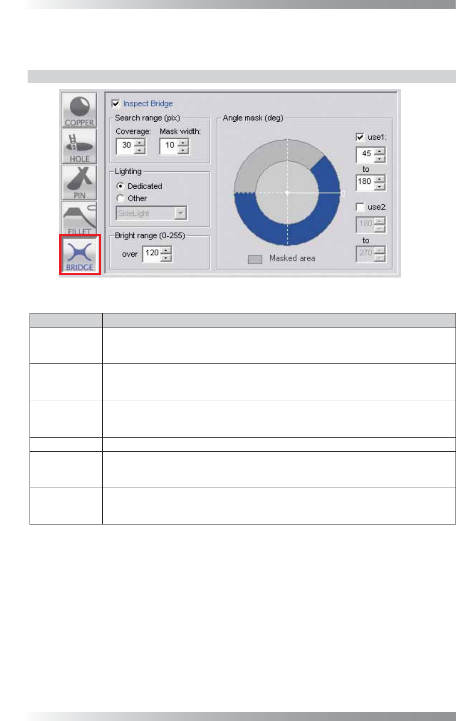
Figure 4-16 Bridge Inspection Setting
Parameter Description
Inspect Bridge
To activate bridge inspection, check Inspect Bridge.
To disable bridge inspection, Un-check Inspect Bridge.
Buttonʼs color is displayed as gray.
Coverage
The inspection area is specifi ed by width (pixel value) from the dotted line circle.
The inspection area is in the green circle except the area netted.
Enter the bigger value to enlarge the inspection area.
Mask width
Specifi es a “no inspection” area in an inspection area set in Coverage by a width (pixels)
from a dotted line circle.
Use this parameter if a pad edge is uneven. Set a mask so a solder fi llet is covered.
Lighting Select a lighting. Default setting is Dedicated.
Bright range
Shows the pixels of a specifi c brightness level which is set in Bright range in yellow.
In Bridge inspection, a yellow area will be searched in an inspection area, and if it
penetrates an inspection area, NG will be reported.
Angle mask
Specifi es a “no inspection” area in an inspection area set in Coverage by angle.
This parameter is used to exclude specifi c angles such as a PCB pattern or silk print
from an inspection area. Two Angle mask can be set.
Table 4-8 Parameter of Bridge Inspection