Programming_mail.pdf - 第28页
I- 20 Programming Manual Part I Basic Operation T ab Item Description Barcode Option Select the Board by Barcode If using barcodes to select data, check Select the Board by Barcode . Compare Barcode Makes comparison with…
I-19
Programming Manual
Part I Basic Operation
Tab Item Description
Signal
OK/NG
Output for
next machine
ON at NG
Turns the signal (OK/NG Out) on if NG is detected.
Turns it off if OK is detected.
ON at OK
Turns the signal (OK/NG Out) to off if NG is
detected. Turns it on if OK is detected.
Reset OK/NG Signal after Unloading PCB
Resets OK/NG signals right after unloading PCB.
For SMEMA Standard
Used to connect to upstream/downstream
machines by SMEMA.
FUJI Mounter Not available.
Output Busy-Out Signal before
Ready-In Signal from next machine
Outputs the Busy Out signal before the Ready-in
signal is input from downstream machines.
Reset Ready Signal after Loading
(No Preconveyor, Not SMEMA)
In the default setting, the Ready Out signal is reset
when a PCB passes an entrance sensor.
When it is set, the Ready Out signal is reset after
the PCB is loaded. Not available with SMEMA.
Reset Ready-Out Signal,
when entrance sensor is touched (QA/QC)
Not available.
Send Ready Signal when there is no PCB
Outputs the Ready signal to upstream machines if
there is no PCB inside the machine.
Set Ready Signal during Unload if inspection is OK
Outputs the Ready signal when unloading a PCB if
an inspection result is OK.
Connect to NG Buffer with Board ID
If using NG buffer, check Connect to NG Buffer
with Board ID.
Send OK/NG, Surface A/B info by Comport
Outputs the OK/NG signal from Comport.
Set Ready Signal when sensor detected
Outputs the Ready signal while the PCB entrance
sensor is activated.
OK/NG Input from
previous machine
ON at NG
Turns the signal (OK/NG Out) on if NG is detected.
Turns it off if OK is detected.
ON at OK
Turns the signal (OK/NG Out) to off if NG is
detected. Turns it on if OK is detected.
OK/NG separated Signal Outputs the OK/NG signal separately.
Barcode
Barcode
Use Barcode Reader
If using a barcode-reader (either fi xed or handy
type), check Use Barcode Reader.
Reader is Set Out of BF
If using a fi xed type barcode-reader, check Reader
is Set Out of BF.
Use Handy Barcode for Hero
Machine
Not available.
Inspect Both Side by One
Barcode
Not available.
Two Dimension Barcode
If using a 2D barcode-reader, check Two
Dimension Barcode.
Not Input Text Reader
If using a barcode-reader used without text input (e.g.,
TOKEN models), check Not Input Text Reader.
Com2 (Com1 Unchecked) Not available.
Print Shift Data (SKP)
Not available.
Multi Head Reader
If using a barcode-reader of multi head, check
Multi Head Reader.
I-20
Programming Manual
Part I Basic Operation
Tab Item Description
Barcode
Option
Select the Board by Barcode
If using barcodes to select data, check Select the
Board by Barcode.
Compare Barcode
Makes comparison with registered barcode information.
Input Barcode on BF-RP1
Enter barcode information on BF-RP1.
Don’t Change Jump Value
To prevent changing the jump setting automatically if an
inspection item is added to or deleted from the data by
the jump function, check Don’t Change Jump Value.
Read Barcode While Loading
Reads barcodes while loading a PCB.
Wait for Barcode Recognition
Retries until a barcode-reader succeeds to read a
barcode.
Don’t Popup Input Dialog while
Read Barcode Error
Outputs the current date name NG fi le if barcode
reading is failed.
Show Skip Message
Displays Some components are skipped to
inspect on the lower left of the screen, if there is a
component to be skipped in an inspection.
Barcode on Two Sides
If managing a number of double-side PCBs by one
barcode, check Barcode on Two Sides.
Change abnormal char to *
Table 2-1
System
Parameter List 1
Tab Item Description
Output File *
Machine *
Conveyor *
Calibration *
Origin *
Hardware1
Conveyor 2 Speed Conveyor
Use if validating a board delay sensor.
Other Items *
Hardware2 *
Camera *
Table 2-2
System
Parameter List 2
CAUTION
Regarding the items with *, these are for Saki engineer only.
I-21
Programming Manual
Part I Basic Operation
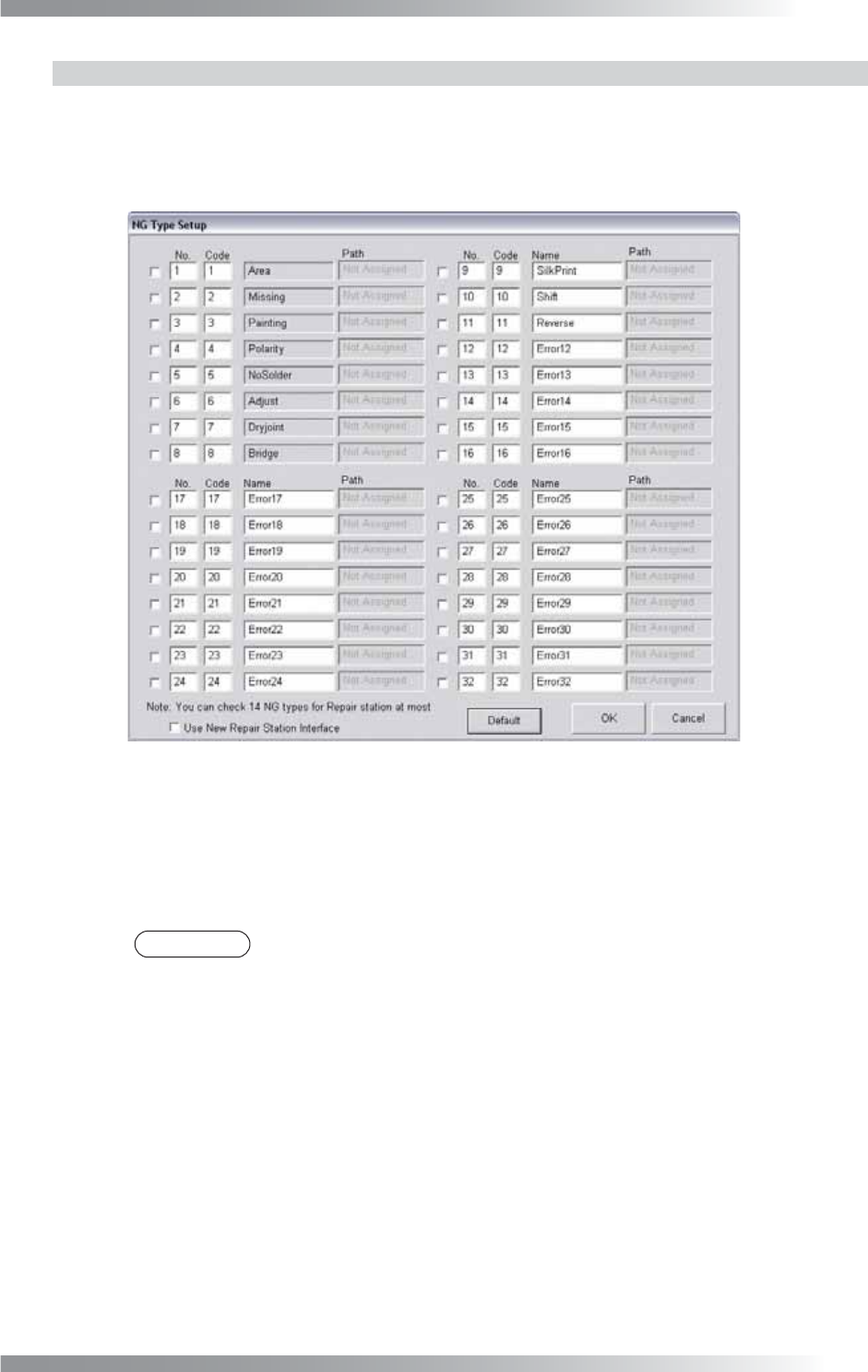
2.1.2 NG Type
Modify the NG type name to appropriate ones. The analysis of the inspection result will be done
effectively based on the proper NG type name.
Step1: Press NG Type in Figure 2-2 System. The NG Type Setup dialog shown in Figure 2-3 appears.
Figure 2-3 NG Type Setup
Step2: 21 NG type names (from 12 to 32) can be modifi ed.
Enter an appropriate name in each Name text-box.
Step3: Press OK to update.
NOTE
Press Default and OK to back to the default setting.