Programming_mail.pdf - 第30页
I- 22 Programming Manual Part I Basic Operation 2.2 Operation Lamp This section describes the settings of signal tower and buzzer . Operations of signal tower lightings and buzzers can be modi fi ed in Operation Lamp acco…
I-21
Programming Manual
Part I Basic Operation
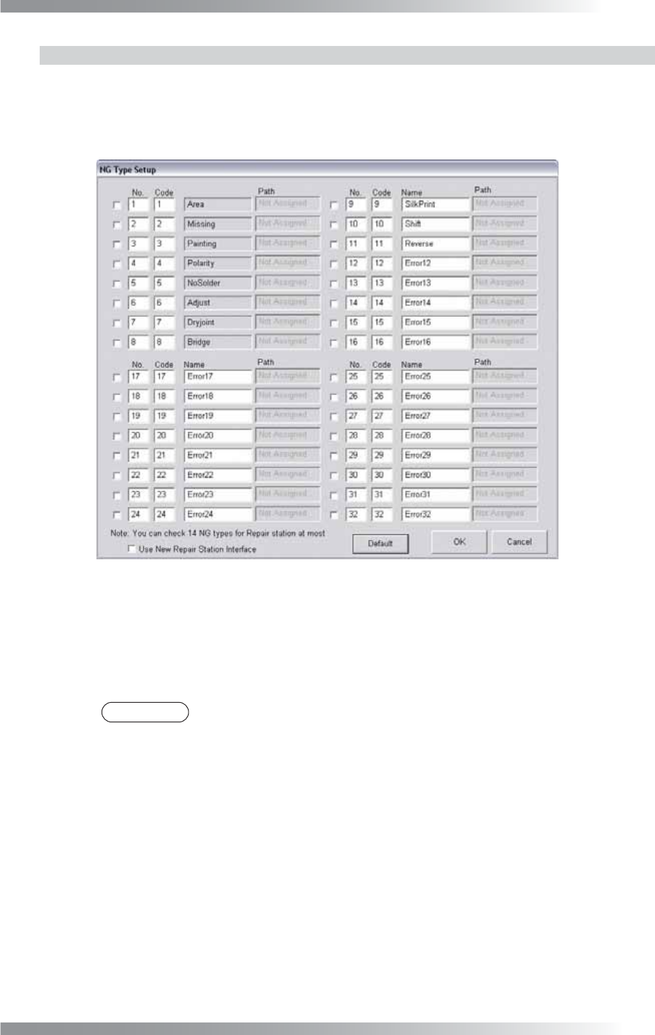
2.1.2 NG Type
Modify the NG type name to appropriate ones. The analysis of the inspection result will be done
effectively based on the proper NG type name.
Step1: Press NG Type in Figure 2-2 System. The NG Type Setup dialog shown in Figure 2-3 appears.
Figure 2-3 NG Type Setup
Step2: 21 NG type names (from 12 to 32) can be modifi ed.
Enter an appropriate name in each Name text-box.
Step3: Press OK to update.
NOTE
Press Default and OK to back to the default setting.
I-22
Programming Manual
Part I Basic Operation
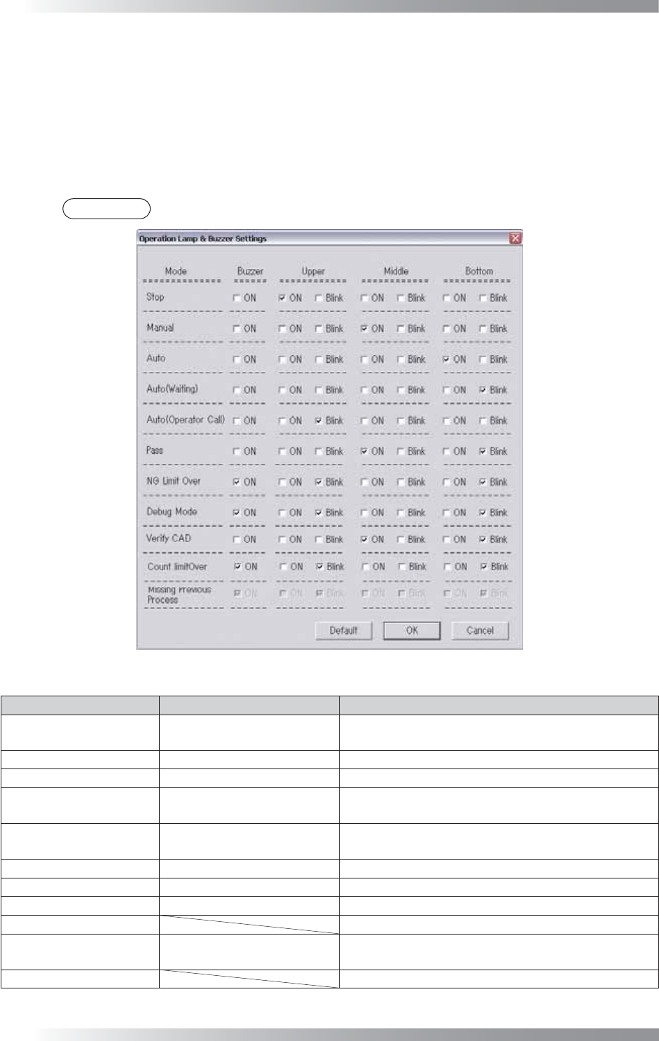
2.2 Operation Lamp
This section describes the settings of signal tower and buzzer.
Operations of signal tower lightings and buzzers can be modifi ed in Operation Lamp according to the
operating condition of the machine.
Press Operation Lamp in Figure 2-1 Select System Setup.
The Operation Lamp and Buzzer Settings dialog shown in Figure 2-4 appears.
Check arbitrary boxes based on the operating condition of the machine.
NOTE
Press Default and OK to back to the default setting.
Figure 2-4 Operation Lamp and Buzzer Settings
Mode State Description
Stop Emergency Stop
Emergency stop switch is pressed or the front door
is opened.
Manual Manual Mode Running Normal operation under Manual Mode.
Auto Auto Mode Running
Normal operation under Auto Mode.
Auto (Waiting)
Waiting for the next PCB Stand-by status for PCB loading under Auto Mode.
Auto (Operator Call)
During Auto Mode Running
Defect Occurrence
Stand-by status for operator check on detected NG
under Auto Mode.
Pass Pass Mode Running
Normal operation in Pass Mode.
NG Limit Over Continuous NG Occurrence
A number of NG PCBs reached to a specifi ed value.
Debug Mode Debug Mode Running
Normal operation in Debug Mode.
Verify CAD Not available.
Count Limit Over
Reached limit number of
inspection
Completed a specifi ed number of PCB inspections.
Missing Previous Process
Not available.
Table 2-3
Operation Lamp and Buzzer Settings
Parameter List
I-23
Programming Manual
Part I Basic Operation
2.3 ALC
This section describes the setting of Automatic Luminance Control.
All parameter is adjusted appropriately at the time of installation or before shipping.
CAUTION
Normally customers do not need to modify the Automatic Luminance Control setting as
wrong setting cause unexpected errors.
2.4 Motor
This section describes settings of Motors.
All parameter is adjusted appropriately at the time of installation or before shipping.
CAUTION
Normally customers do not need to modify the Automatic Luminance Control setting as
wrong setting cause unexpected errors.
2.5 Marking
This section describes how to set the marking function.
Collective Setting and Setting by Type of Marking are available to set the marking function.
If both are selected, Setting by Type of Marking will be used.
CAUTION
This function is available only on models with marking units.
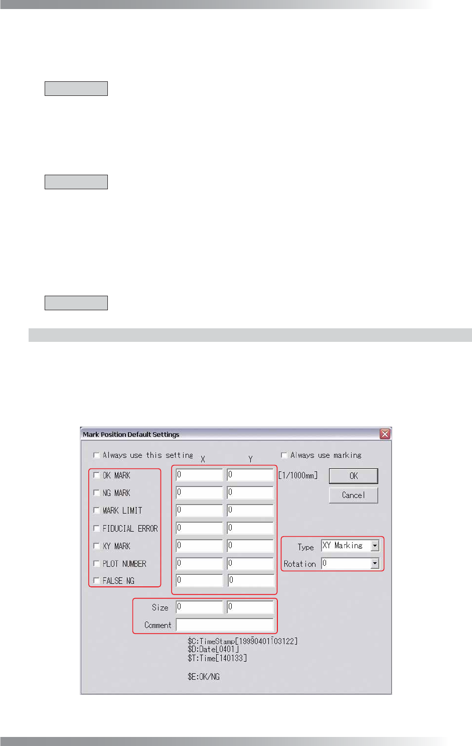
2.5.1 Collective Setting
Press Marking in Figure 2-1 Select System Setup.
The Mark Position Default Settings dialog shown in Figure 2-5 appears.
A in Figure 2-5 specifi es a type of a marking. B specifi es a position of a marking. C specifi es a plot
selection of an XY marking and a rotation angle of characters by PLOT NUMBER when plotting.
D specifi es a size of characters and a content of a comment (in the case of selecting PLOT NUMBER).
A
B
D
C
Figure 2-5 Mark Position Default Settings