Programming_mail.pdf - 第54页
II- 10 Programming Manual Part II Inspection Data Step15: The part of CAD data which is not speci fi ed as component data is displayed. Specify conditions to extract PCB size and PCB thickness from data. These data will b…
II-9
Programming Manual
Part II Inspection Data
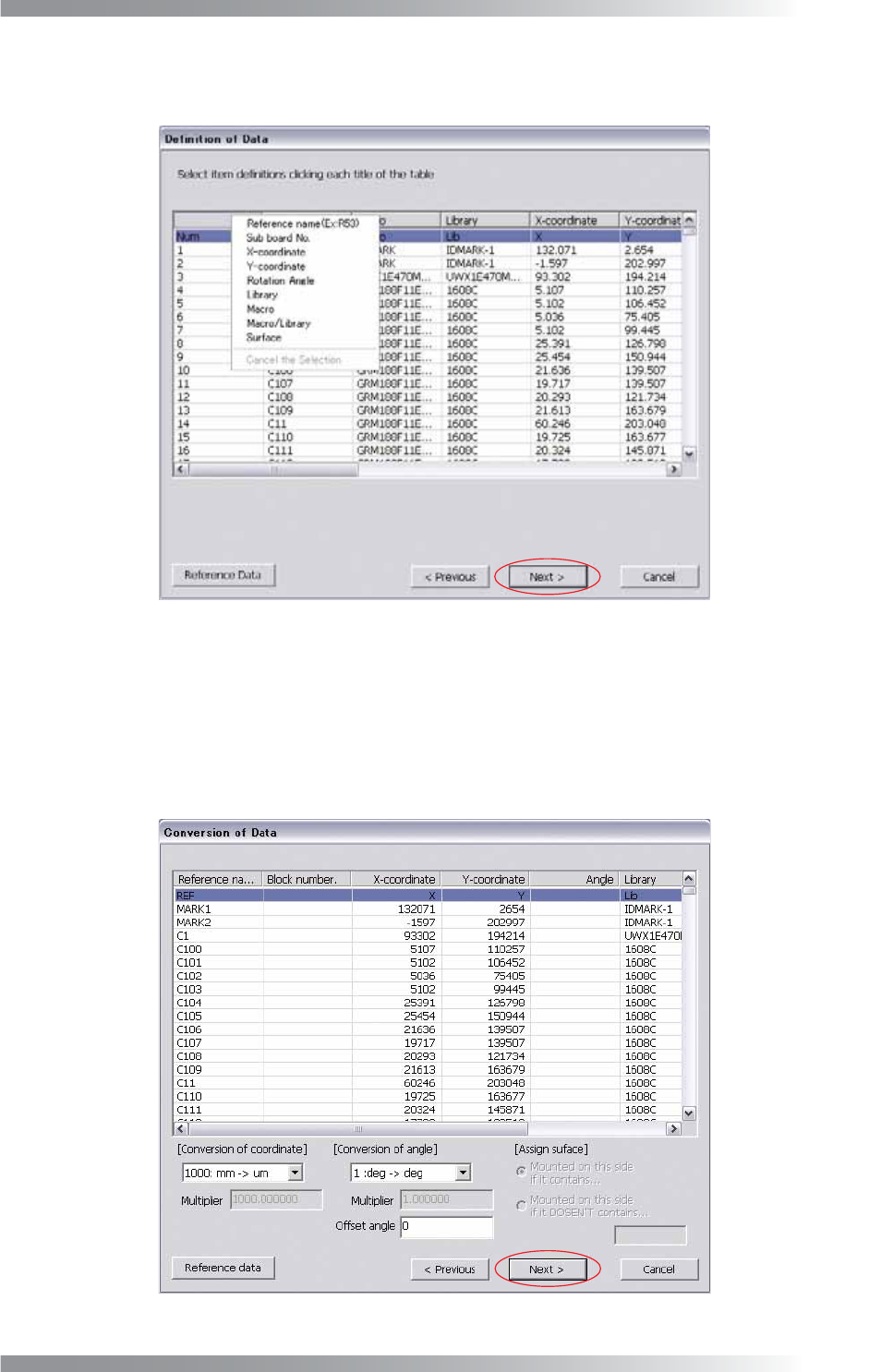
Step13: Press each column header. Parameterʼs items are displayed as shown in Figure 1-12. Select a
parameter that matches with each column. After all the settings are completed, press Next.
Figure 1-12 Defi nition of Data
Step14: Specify conversion conditions for a coordinate and an angle. Select items from the drop-down list.
Multiplier is available if Other is selected from the drop-down list. If an offset angle is entered in
the Offset angle fi eld, the specifi ed amount of offset will be added to all the component rotation.
If Surface is specifi ed in Step13, enter an appropriate parameter in the Assign surface fi eld.
After all the settings are completed, press Next.
Figure 1-13 Data Conversion
II-10
Programming Manual
Part II Inspection Data
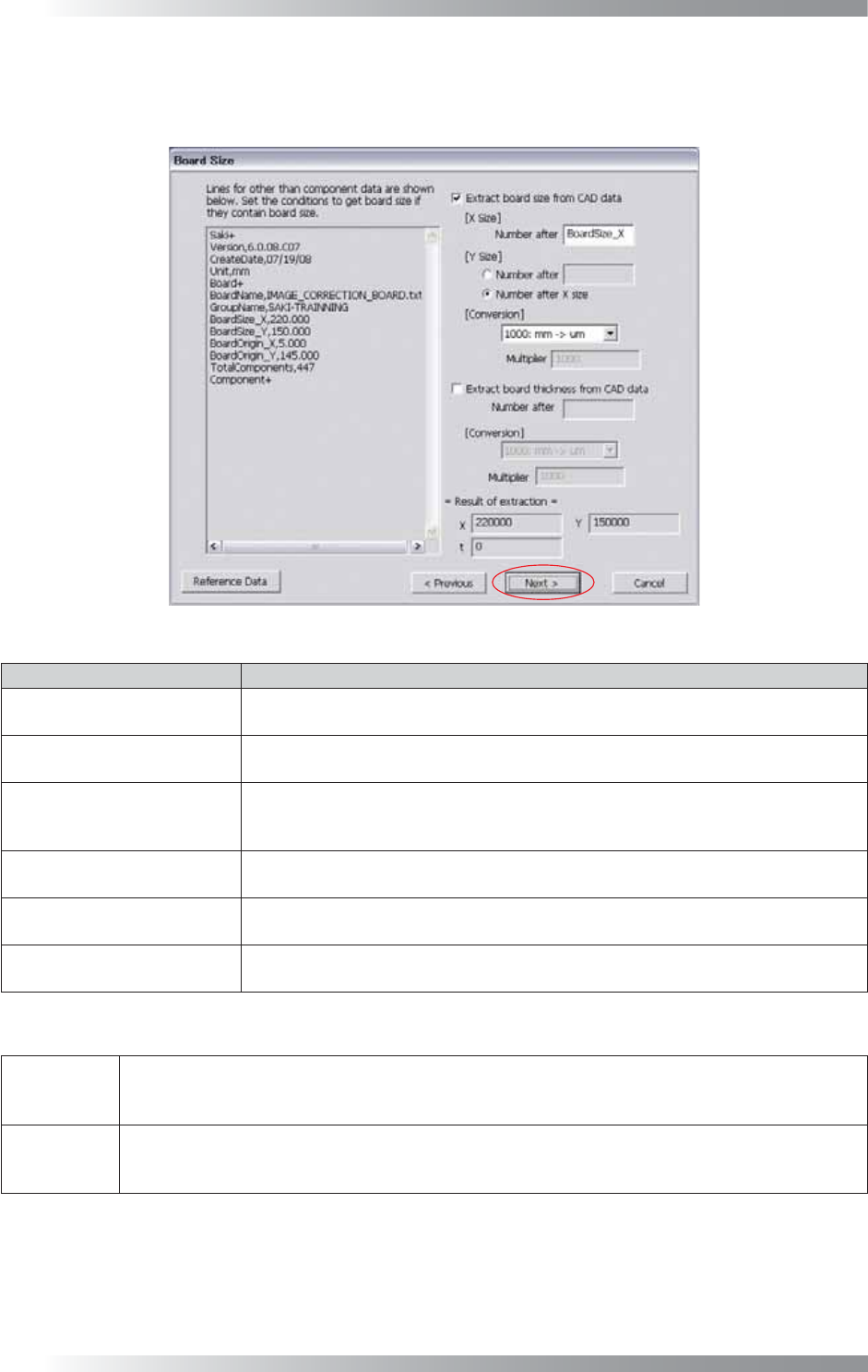
Step15: The part of CAD data which is not specifi ed as component data is displayed. Specify conditions to
extract PCB size and PCB thickness from data. These data will be automatically extracted from the
next time.
Figure 1-14 Extract PCB Size
Item Description
Extract board size from
CAD data
To extract lengths of the X direction and Y direction of a PCB, check Extract
board size from CAD data.
X Size
Enter the character preceding the number which shows the X direction length of a
PCB. The extracted value is displayed in Result of extraction.
Y Size
Enter the character preceding the number which shows the Y direction length of a
PCB. Check Number after X size if lengths of X direction and Y direction are
continuing. The extracted value is displayed in Result of extraction.
Conversion
Select conversion conditions from the drop-down list. Select Other from the drop-
down list and enter a multiplier in the Multiplier fi eld.
Extract board thickness from
CAD data
To extract PCB thickness, check Extract board thickness from CAD data.
Enter the character preceding the number which shows the PCB thickness.
Conversion
Select conversion conditions from the drop-down list. Select Other from the drop-
down list and enter a multiplier in the Multiplier fi eld.
Table 1-7 Description of Parameters
CAD Data
Board+
BoardSize_X,220.000
(Next value of BoardSize_X is always the length of the X direction of the PCB)
BoardSize_Y,150.000
(Next value of BoardSize_Y is always the length of the Y direction of the PCB)
Settings
Enter BoardSize_X in the X Size fi eld.
Enter BoardSize_Y in the Y Size fi eld (It can be substituted by checking Number after X size).
Select mm→μm from the drop-down list of Conversion.
Table 1-8 Example
II-11
Programming Manual
Part II Inspection Data
Step16: Press Next to enter PCB size and PCB thickness manually. Enter necessary conditions to extract
these data automatically. Make sure that necessary data is correctly extracted in Result of
extraction, and press Next.
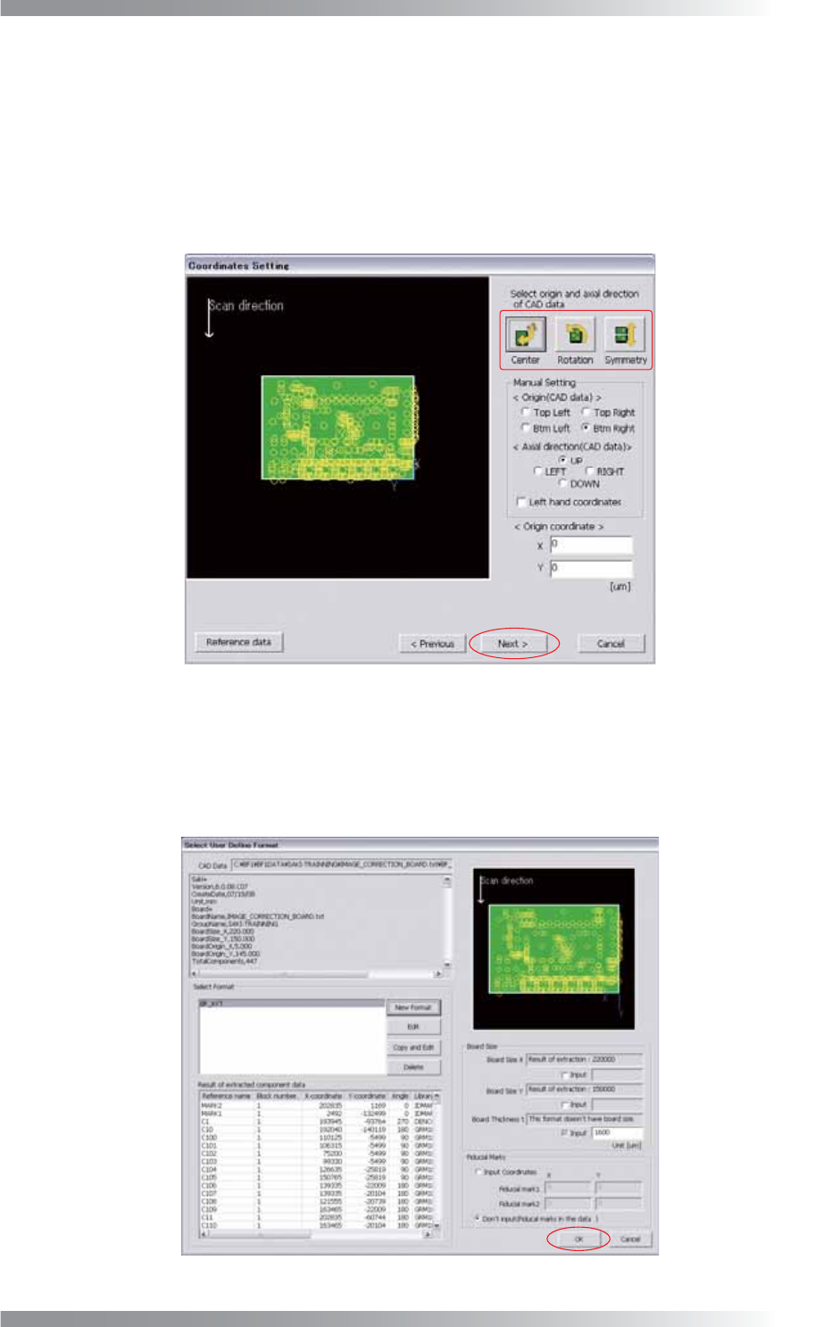
Step17: Press three buttons to match a CAD data origin with a machine origin. Starting from the left, Place
all data position inside of the PCB, Rotate all data 90° in counterclockwise direction, Flip all
data vertical. After all the settings are completed, press Next.
Figure 1-15 Coordinates Setting
Step18: Make sure that the component data is shown on the PCB image and Board Size is displayed.
If the data is not automatically extracted, enter the PCB size manually.
If the fi ducial mark data is not in the data, check Input coordinates and enter arbitrary
coordinates. After all the settings are completed, press OK.
Figure 1-16 User Defi ne Format