Programming_mail.pdf - 第191页
Programming Manual Part V Other Function V- 1 Other Function
IV-26
Programming Manual
Part IV Option Setting
4.3 Inspection Image
Combining three different LED lighting, TopLight (Coaxial Overhead illumination), SideLight, and LowLight,
create the most appropriate image for the inspection.
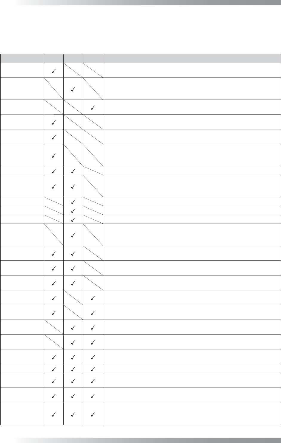
Lighting Top
Side
Low Description
TopLight
Image scanned with TopLight. TopLight is suitable for solder inspection
to shed light from the overhead.
SideLight
Image scanned with SideLight. Nearly visual color repeatability lighting
and a dark part becomes bright. SideLight is suitable for inspection
using colors.
LowLight
Image scanned with LowLight. Silk characters or characters on a component
become bright. LowLight is suitable for character inspection.
Density
Image that gamma-corrected TopLight brightness level. Density is suitable
for denoising of TopLight.
Outline
Image that doubled TopLight brightness level. Outline is suitable for contour
extraction of component.
MultiColorEx
Image that converted TopLight brightness into hue information. Bright
part is converted to look like red and dark part is converted to look like
blue. MultiColorEx is suitable for solder inspection.
Add
Image that totaled brightness of TopLight and SideLight.
Add3
Image that totaled brightness of TopLight and SideLight, and in addition
highlighted bright parts and dark parts. Add3 is suitable for inspection of
fi ducial mark or misalignment correction.
RED
Image that outputs constituent of Red at the 256 shades of gray from 0 to 255.
GREEN
Image that outputs constituent of Green at the 256 shades of gray from 0 to 255.
BLUE
Image that outputs constituent of Blue at the 256 shades of gray from 0 to 255.
HSV_Color
Image that converted SideLight brightness to HSV format. It is possible
to highlight the specifi c color information. Each HSV parameter can be
set optionally from Set.
Two Red-TOP
Image that subtracted TopLight brightness from double Red constituent. Two
Red-TOP is suitable for extract of laser-printed characters such as barcode.
TOP-SIDE
Image that subtracted SideLight brightness from TopLight brightness.
TOP-SIDE is suitable for extract (highlight) of plain surface.
SIDE-TOP
Image that subtracted TopLight brightness from SideLight brightness.
SIDE-TOP is suitable for extract (highlight) of inclined surface.
TOP-LOW
Image that subtracted LowLight brightness from TopLight brightness.
TOP-LOW is suitable for solder inspection to appear fi llet part darkly.
LOW-TOP
Image that subtracted TopLight brightness from LowLight brightness.
Silk characters or plain surface becomes brightly.
SIDE-LOW
Image that subtracted LowLight brightness from SideLight brightness.
Silk characters or plain surface becomes brightly.
LOW-SIDE
Image that subtracted SideLight brightness from LowLight brightness.
LOW-SIDE is suitable for extract (highlight) of inclined surface.
Multi-Lighting
Image that can clearly display fi llet shape by color. Outputting red in
case of TopLight, green in case of SideLight, or blue in case of LowLight.
TOPSIDELOW
Brightness of TopLight, SideLight, and LowLight can be set freely.
UserDefi ne
Brightness of TopLight, SideLight, and LowLight can be set freely.
UserDefi ne can set more fl exible than TopSideLow.
SPECT
Image that converted brightness into hue information. SPECT is used
in Algorithm IC_Solder2 and IC_Solder3.
OKNGColors
OKNGColors separates between OK color as white and NG color as
black. It is possible to detect the difference of similar colors. OKNGColors
can be used in fare-paying software.
Table 4-1 Description of Each Image

Programming Manual
Part V Other Function
V-
1
Other Function
V-2
Programming Manual
Part V Other Function
1 KPK
KPK (Key-colors Peak Keeping method) is a new inspection solution, which allows easier programming for
missing inspection in terms of operation and speed. KPK is compatible with other functions of inspection
software. By the combination use with existing inspection algorithm, missing inspection can be enhanced
further. KPK data can be added to the existing inspection data. KPK can be used in fare-paying software.
CAUTION
If inspection data is made by auto deployment and library assignment after making KPK data, KPK
library will be overwritten.
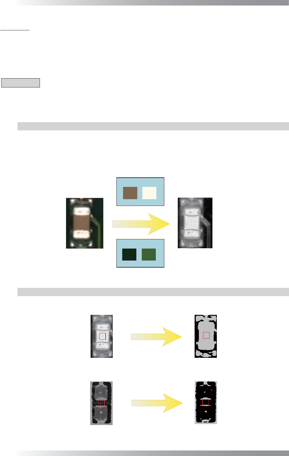
1.1 Inspection Overview
1.1.1 OKNGColors Lighting
OKNGColors lighting separates between OK color as white and NG color as black by registering OK
and NG colors in advance. If the color of the detected area is closer to the one registered as OK color,
the area would become brighter. If the color of the detected area is closer to the one registered as
NG color, the area would become darker. To set component colors as OK color and PCB colors as
NG color, component color would become white and PCB color would become black.
Body Electrode
OK Colors
NG Colors
(a) Side
(b) OKNGColors
PCB
Figure 1-1 OKNGColors Lighting
1.1.2 Inspection Method
KPK uses Black/White algorithm which calculates the percentage of the area where the pixel is
brighter. If the percentage of the area where the pixel is brighter, the result will be missing.
Black/White
Black/White
OK Component
Missing Component
100%
Calculates the percentage of the area
Image of OKNGColors
10%
OK
NG
where the pixel is brighter
Figure 1-2 Inspection Method