Programming_mail.pdf - 第196页
V- 6 Programming Manual Part V Other Function Step3: Press Extract Colors Automatically from Bare Board Image in Figure 1-6. The dialog shown in Figure 1-8 appears. Figure 1-8 Auto Extraction of Bare PCB Image Step4: Adj…
V-5
Programming Manual
Part V Other Function
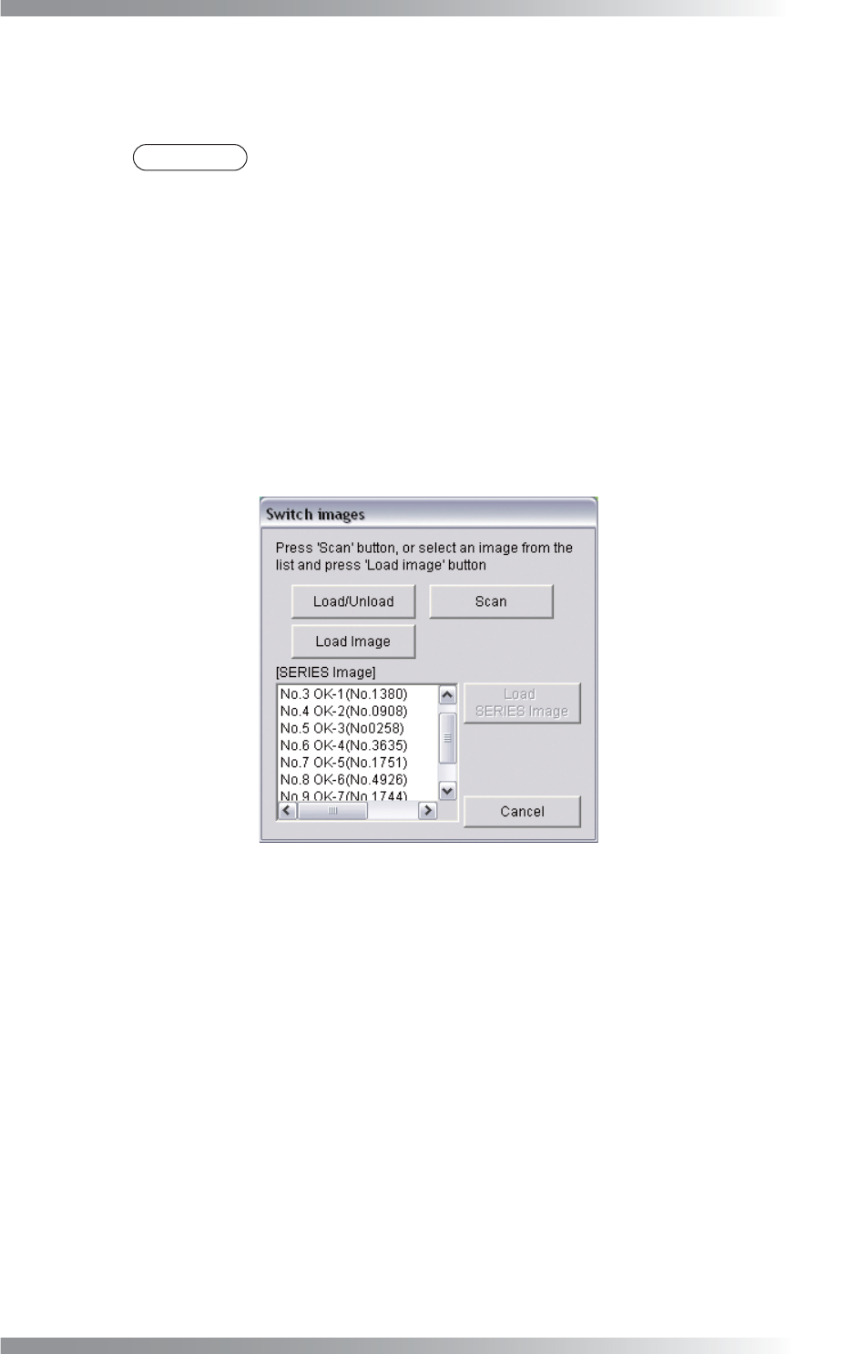
Step2: If bare PCBs are already scanned and saved, select the fi le from the SERIES Image list-
box, and press Load SERIES Image. If no series image is saved, procedures depend on
machine type benchtop machine, inline machine or BF-Editor.
NOTE
Series image indicates series of inspection images stored in the SERIES folder
under a board name folder.
In case of benchtop machines
Load the PCB to the machine and press Scan.
In case of inline machines
Adjust conveyor rail width and set the PCB on conveyor rail. Press Load / Unload.
Set the PCB in the machine and press Scan. To unload the PCB, press Load / Unload.
In case of BF-Editor
Press Load Image and select TOPLIGHT.BMP saved in arbitrary folder.
(e.g., D:\BF1\BF1DATA\Inspection Group Name\PCB Name folder)
Figure 1-7 Switch Images 2
V-6
Programming Manual
Part V Other Function
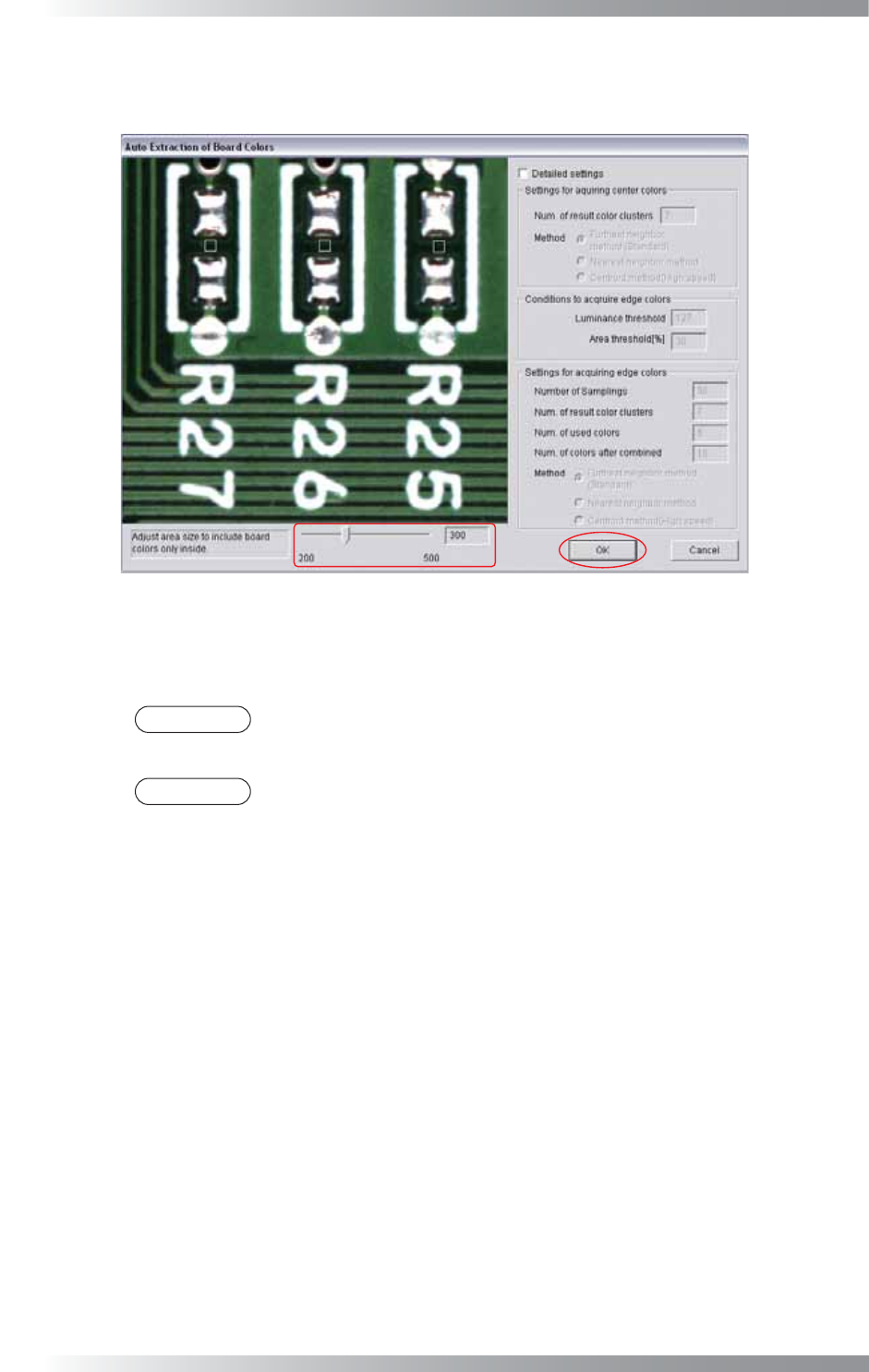
Step3: Press Extract Colors Automatically from Bare Board Image in Figure 1-6.
The dialog shown in Figure 1-8 appears.
Figure 1-8 Auto Extraction of Bare PCB Image
Step4: Adjust the window size to extract component color by moving a slide-bar. The window size
is area to extract PCB color. Press OK and start PCB color extraction.
NOTE
The specifi ed window size is common to all components data. Therefore make the
window size in accordance with the minimum component size.
NOTE
No need for Detailed settings.
Step5: Make sure that the PCB color is displayed in black. The closer the PCB color is to the
extracted PCB color, the darker it displays. Refer to 1.2.3 Auto Deployment of KPK.
V-7
Programming Manual
Part V Other Function
1.2.2 No Bare PCB
Registers the PCB color under the component as NG color.
Step1: Click the parts to be registered as NG colors and press Add Current Color.
NG color is displayed in the Assignment Color list-box.
The area which color is similar to the registered color is displayed in black on the right image.
Continue to register all NG colors in the list-box until the NG area is displayed in black.
NOTE
Maximum 10 colors can be registered.
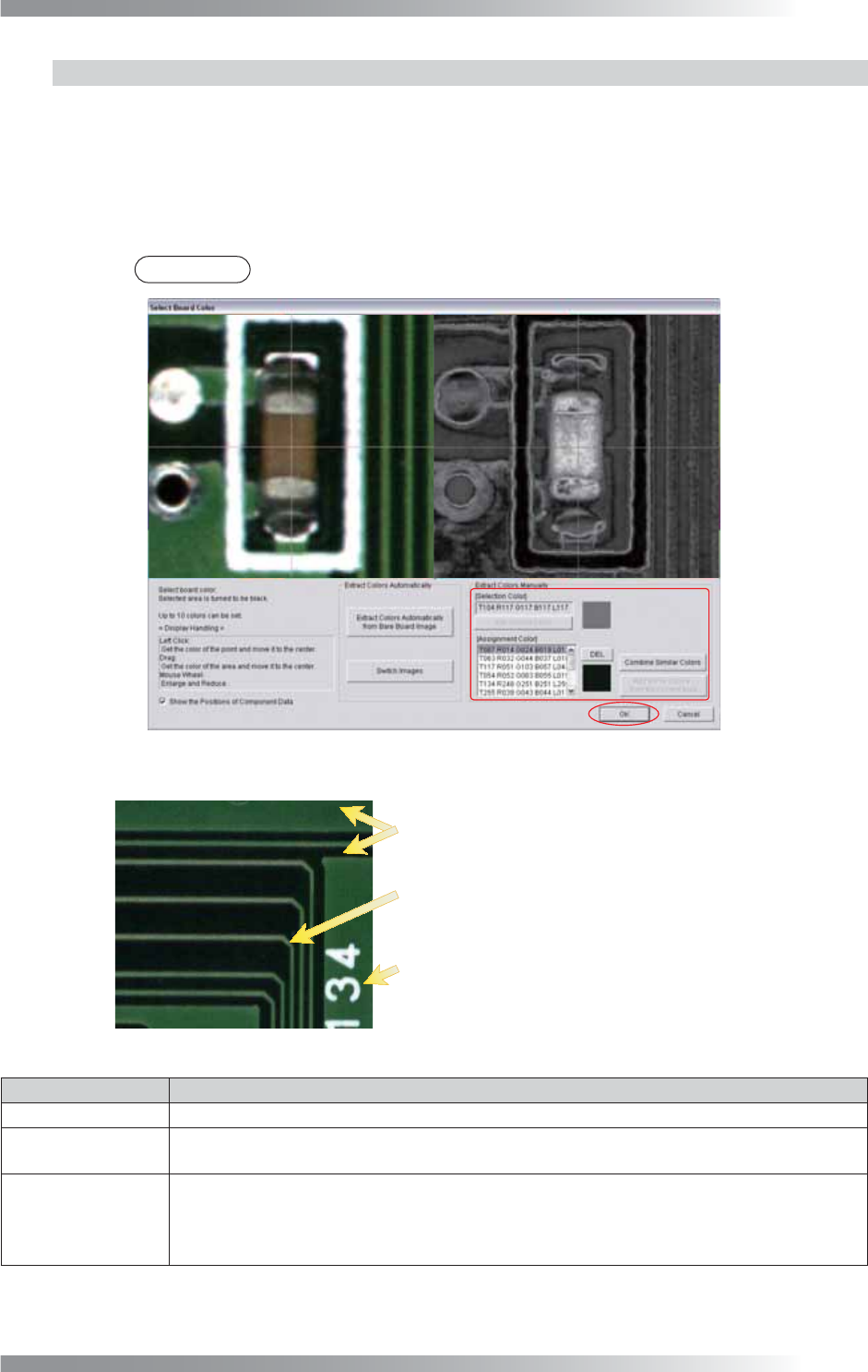
Figure 1-9 Extract Colors Manually
Register PCB surface color and resist surface color.
Register the pattern color as NG color
Register the silk color as NG color
if it is different from the resist surface color.
if the silk printing is under components.
Figure 1-10 Register NG Colors
Item Description
DEL Select the color in the list-box and press DEL to delete the color.
Combine Similar
Colors
Press Combine Similar Colors and the dialog shown in Figure 1-11 appears. Press OK to
combine the selected two similar colors to decrease the number of registered colors.
Add Some Colors
from the Current
Area
Select the area which color is to be registered as NG. Press Add Some Colors from the
Current Area and the dialog shown in Figure 1-12 appears. Press OK and the dialog shown
in Figure 1-13 appears. The extracted colors are displayed. To register the color as NG
colors, check Set as NG Color and press OK.
Table 1-1 Each Item of Extract Colors Manually