Programming_mail.pdf - 第209页
V- 19 Programming Manual Part V Other Function Step2: ECD setting dialog appears. Check Mark1 , Mark2 , Sampling , and Lighting of Default Parameters . Press OK . No need to set for Statistical Process and Template Match…
V-18
Programming Manual
Part V Other Function
2 ECD
ECD (Extra Component Detection) is a function to detect extra component which is fallen and attached to
the area other than the component mounting area from any cause.
2.1 Inspection Overview
Sample several OK PCBs and make template images. Extra component is detected based on the difference
of template images and inspection PCB images. ECD enables to inspect entire PCB with one inspection
window.
2.2 Inspection Procedure
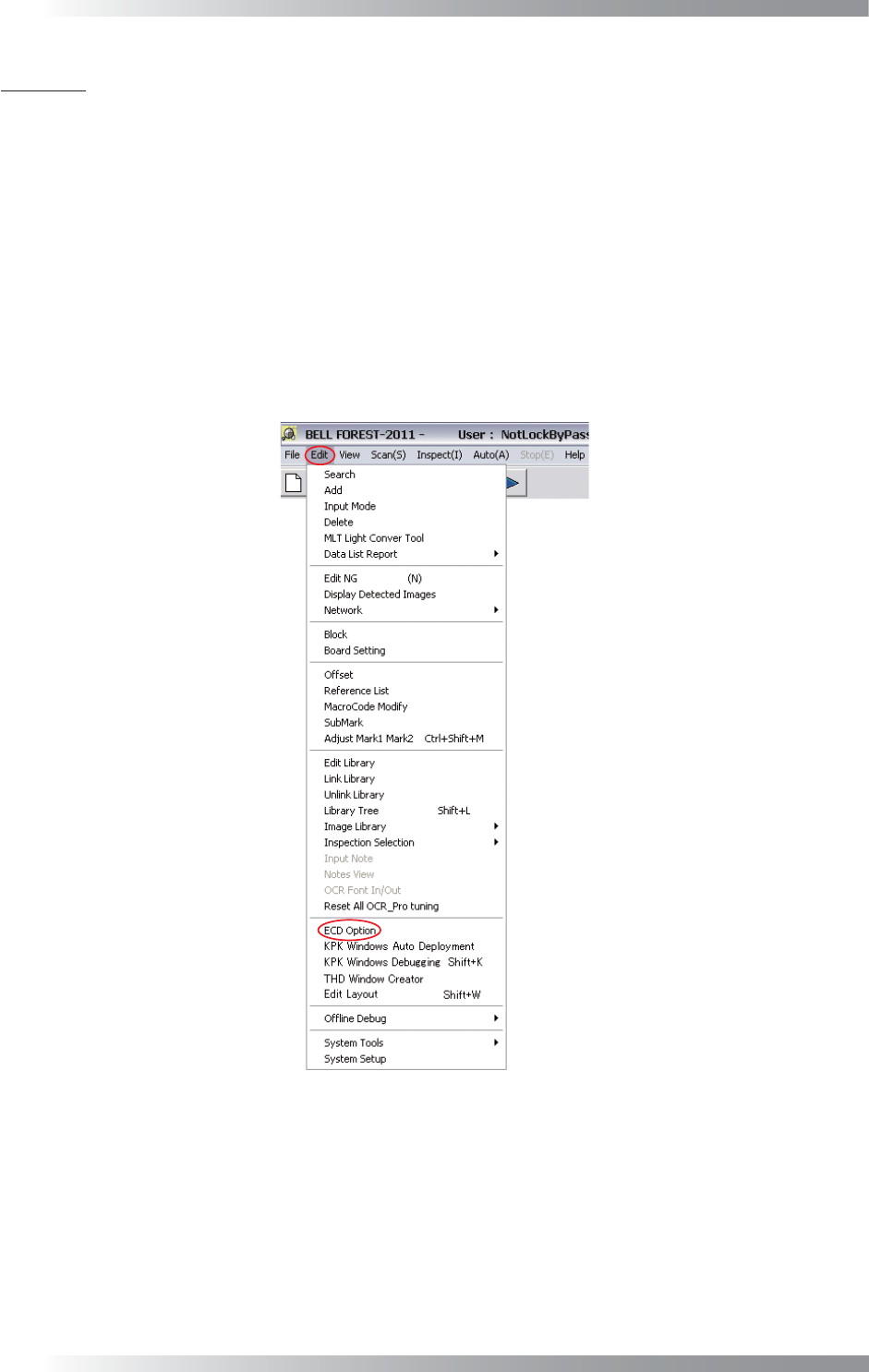
Step1: Select Edit > ECD Option from the menu-bar.
Figure 2-1 ECD Option
V-19
Programming Manual
Part V Other Function
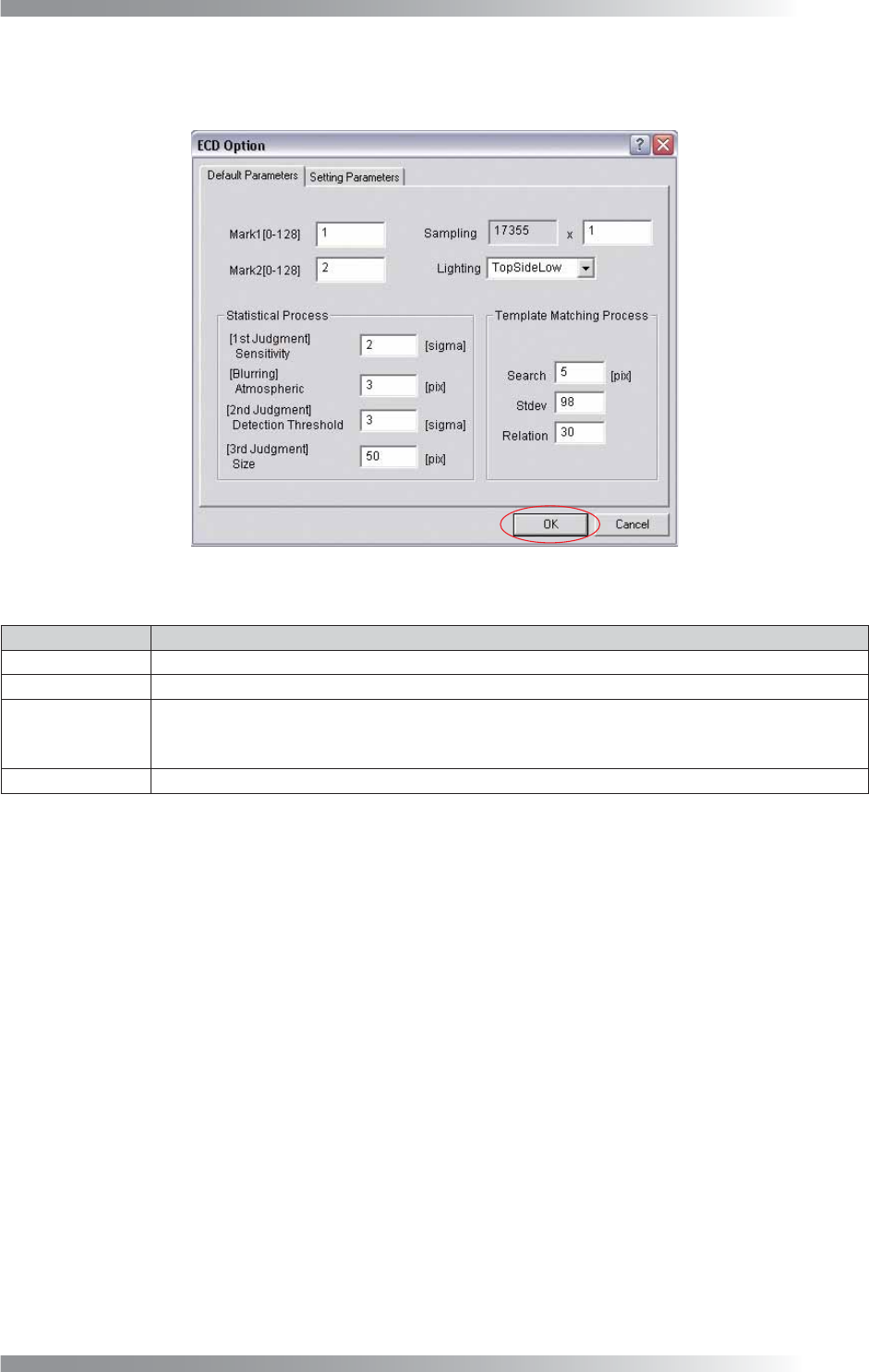
Step2: ECD setting dialog appears. Check Mark1, Mark2, Sampling, and Lighting of Default Parameters.
Press OK. No need to set for Statistical Process and Template Matching Process.
Figure 2-2 ECD Default Setting
Item Description
MARK1 [0-128] Enter 1.
MARK2 [0-128] Enter 2.
Sampling
Set the pixel interval to extract brightness. If setting value is 6, extract brightness at intervals of
6 pixels. If resolution is 10 μm, enter 6 or greater. If resolution is 18 μm, enter 4 or greater.
Enter the bigger value to turn down the resolution accelerate the inspection speed.
Lighting Select TopSideLow.
Table 2-1 ECD Default Setting
V-20
Programming Manual
Part V Other Function
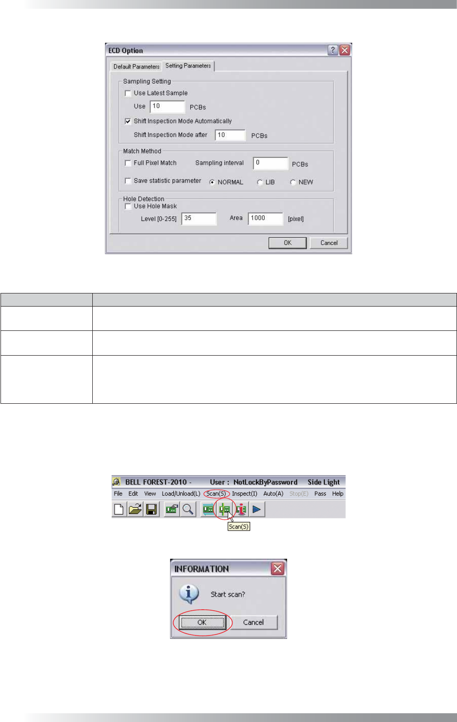
Figure 2-3 Parameter Setting
Item Description
Use Latest Sample
Latest OK image is used as template image.
Specify the number of PCBs in Use Latest.
Shift Inspection
Mode Automatically
The mode will be switched to inspection mode automatically after sampling is completed.
Default number of sampled PCB is 10.
Use Hole Mask
Excludes the through hole of PCB from inspection target.
Specify the brightness level of through hole in Level fi eld.
Specify the area of through holes in the Area fi eld. Areas darker than Level and larger than
Area will be judged as through hole and will not be inspected.
Table 2-2 Parameter Setting
Step3: Set the OK PCB. Press Scan button on the tool-bar or select Scan from the menu-bar. The dialog
shown in Figure 2-5 appears. Press OK.
Figure 2-4 Scan
Figure 2-5 Check Auto Inspection Start