Programming_mail.pdf - 第193页
V- 3 Programming Manual Part V Other Function 1.2 Mak e KPK Data Step1: Open KPK setting dialog. Select Edit > KPK Windows Auto Deployment from the menu-bar to add KPK in existing inspection data. Figure 1-3 KPK Windo…
V-2
Programming Manual
Part V Other Function
1 KPK
KPK (Key-colors Peak Keeping method) is a new inspection solution, which allows easier programming for
missing inspection in terms of operation and speed. KPK is compatible with other functions of inspection
software. By the combination use with existing inspection algorithm, missing inspection can be enhanced
further. KPK data can be added to the existing inspection data. KPK can be used in fare-paying software.
CAUTION
If inspection data is made by auto deployment and library assignment after making KPK data, KPK
library will be overwritten.
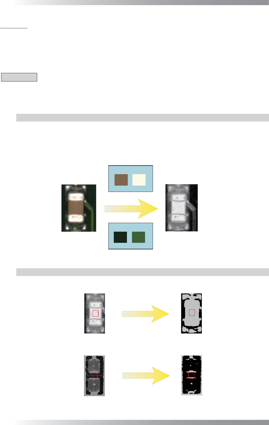
1.1 Inspection Overview
1.1.1 OKNGColors Lighting
OKNGColors lighting separates between OK color as white and NG color as black by registering OK
and NG colors in advance. If the color of the detected area is closer to the one registered as OK color,
the area would become brighter. If the color of the detected area is closer to the one registered as
NG color, the area would become darker. To set component colors as OK color and PCB colors as
NG color, component color would become white and PCB color would become black.
Body Electrode
OK Colors
NG Colors
(a) Side
(b) OKNGColors
PCB
Figure 1-1 OKNGColors Lighting
1.1.2 Inspection Method
KPK uses Black/White algorithm which calculates the percentage of the area where the pixel is
brighter. If the percentage of the area where the pixel is brighter, the result will be missing.
Black/White
Black/White
OK Component
Missing Component
100%
Calculates the percentage of the area
Image of OKNGColors
10%
OK
NG
where the pixel is brighter
Figure 1-2 Inspection Method
V-3
Programming Manual
Part V Other Function
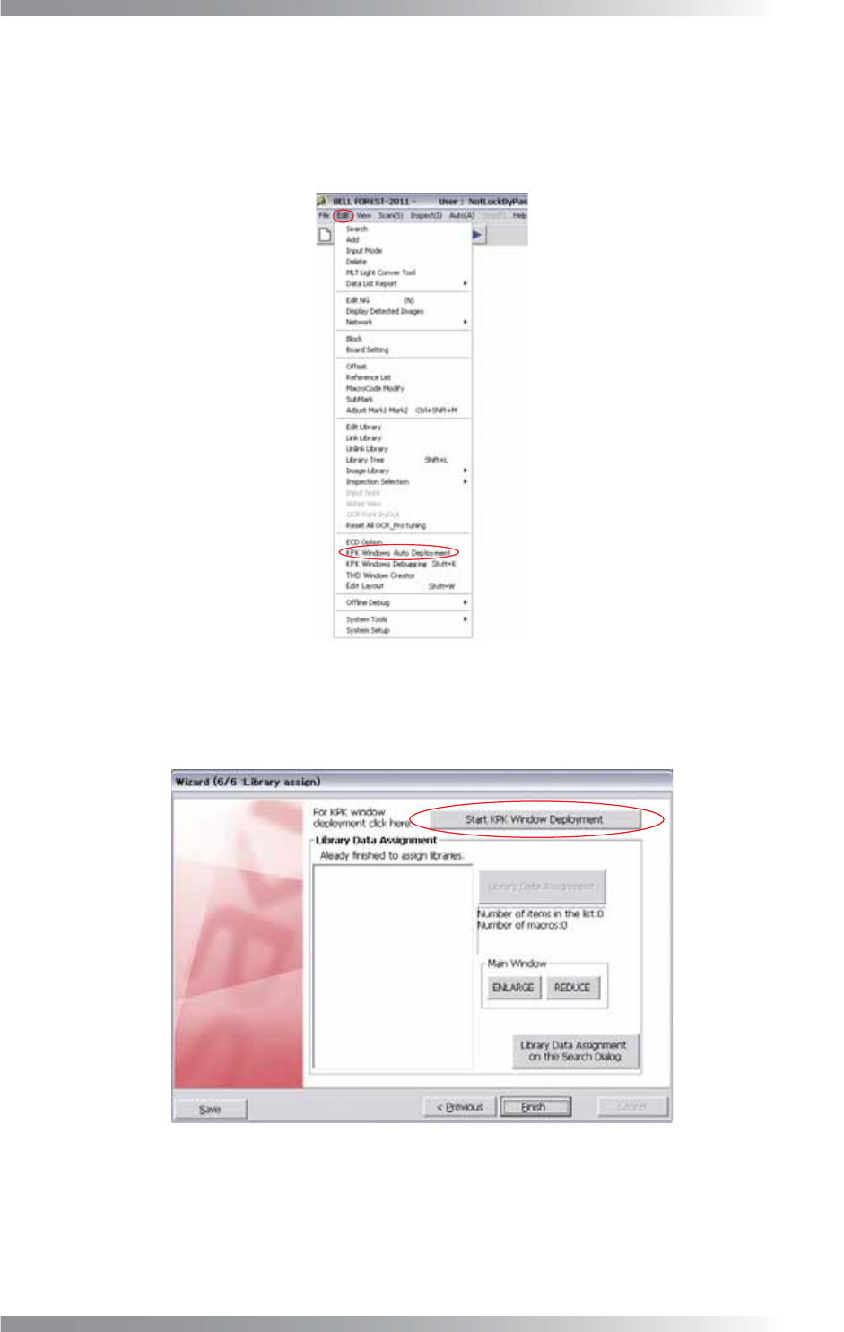
1.2 Make KPK Data
Step1: Open KPK setting dialog.
Select Edit > KPK Windows Auto Deployment from the menu-bar to add KPK in existing
inspection data.
Figure 1-3 KPK Windows Auto Deployment
Refer to Part II 1.1 Make Inspection Data on AOI Machine to make new inspection data and
press Start KPK Window Deployment in Step43.
Figure 1-4 KPK Deployment
V-4
Programming Manual
Part V Other Function
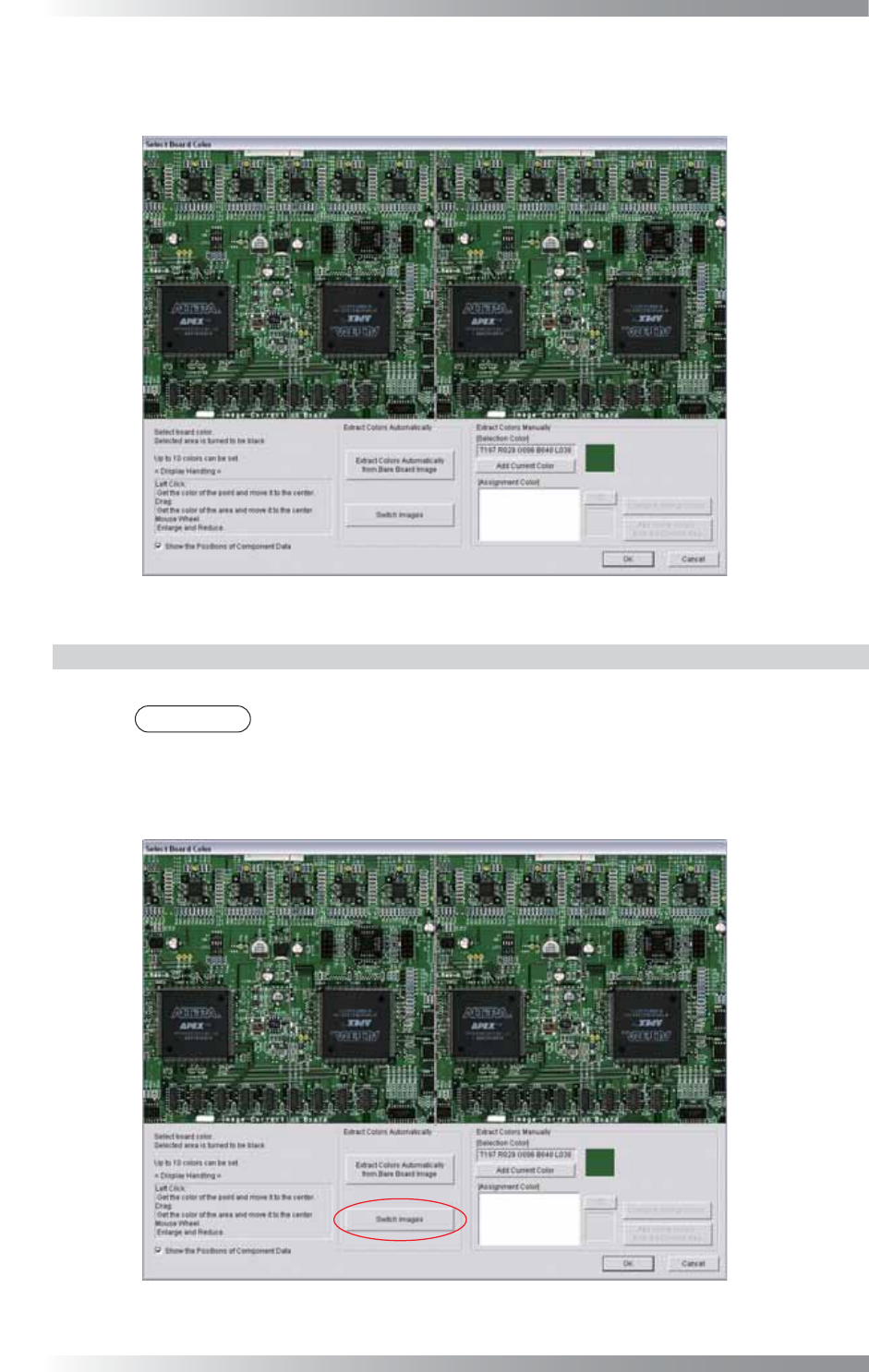
Step2: The dialog shown in Figure 1-5 appears. Register the PCB color as NG color.
Procedures depend on the presence or absence of bare PCB.
Figure 1-5 Specify PCB Color
1.2.1 With Bare PCB
Extracts a PCB color from a bare PCB and register it as an NG color.
NOTE
In the case of using KPK for post-refl ow inspection, it is recommended to use a bare
PCB after refl ow-oven. That is able to reduce color variation caused by fl ux and to
extract PCB color properly.
Step1: Press Switch Images.
Figure 1-6 Switch Images 1