Programming_mail.pdf - 第97页
III- 23 Programming Manual Part III Inspection Algorithm 1.9.5 Use of Av era ge Polarity inspections by using A verage provide higher accuracy . In case of SOP , the algorithm makes an inspection window on a point-symmet…
III-22
Programming Manual
Part III Inspection Algorithm
1.9.4 Setting Procedure of Polarity Inspection
Step1: Select a lighting that a polarity is visually clear from the Lighting drop-down list.
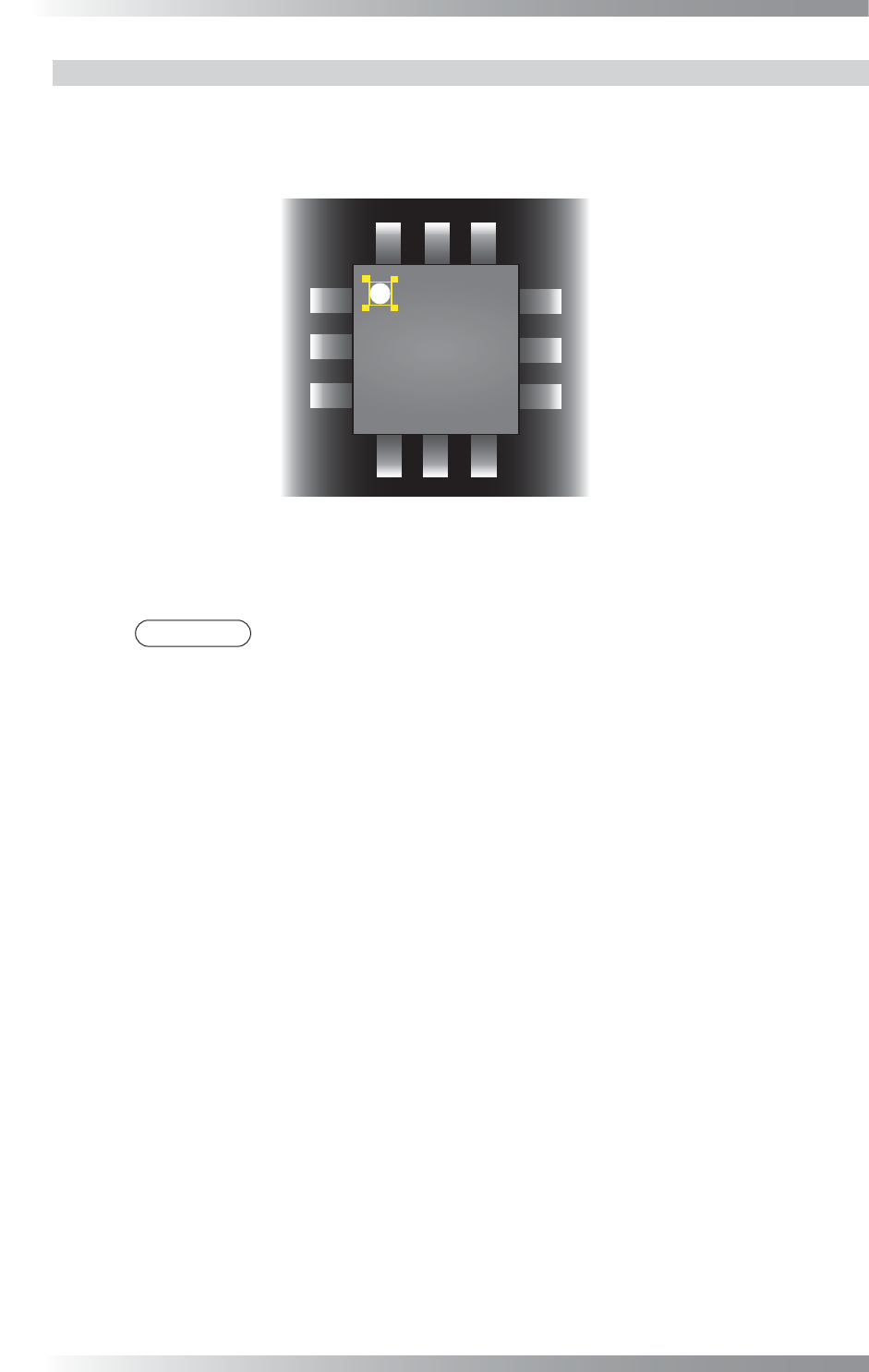
Step2: Adjust the Range inspection window position to surround the polarity mark.
Figure 1-26 Inspection Window for Polarity Inspection
Step3: Make sure that the sample value is in the OK range.
If it is out of OK range, adjust value in the Lower fi eld.
NOTE
Sample value is the subtracted value between maximum and minimum brightness
level inside the inspection window.
Step4: Enter the appropriate vector into the Shift fi eld by selecting from V1 to V8 according to the
vector used in the Memorize to fi eld in the Adjust window.
Step5: Press Inspect. Make sure that the inspection is completed properly.
III-23
Programming Manual
Part III Inspection Algorithm
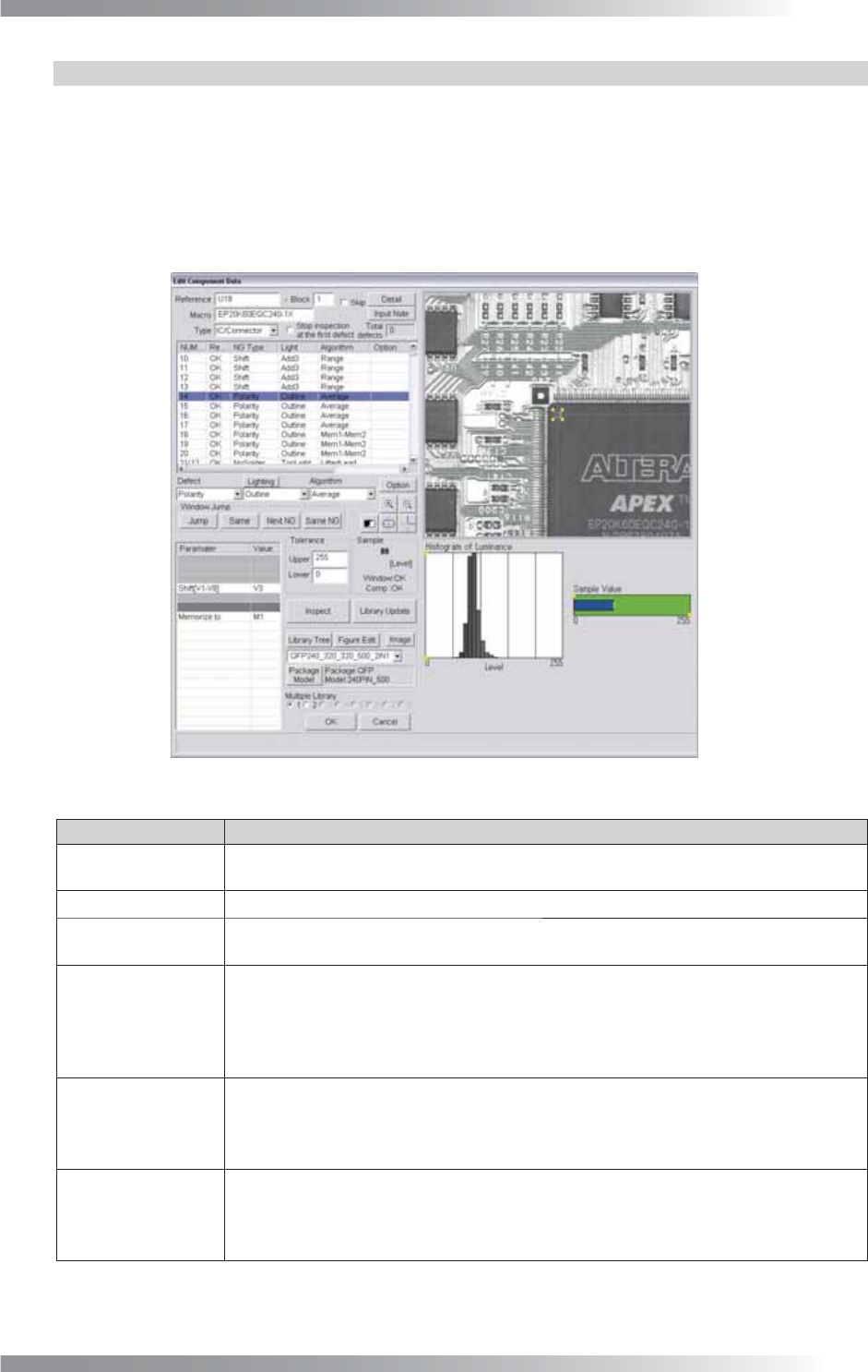
1.9.5 Use of Average
Polarity inspections by using Average provide higher accuracy.
In case of SOP, the algorithm makes an inspection window on a point-symmetric point of a polarity mark.
It calculates brightness level differences between inspection windows to reduce the effect of dusts or
noises.
In case of QFP, the algorithm makes an inspection window on a point-symmetric point and line-symmetric
point of a polarity mark. It calculates brightness level differences between inspection windows.
Figure 1-27 Average (Polarity)
Parameter Description
Lighting
Select a lighting that the brightness level difference between the polarity and the
surface is visually clear.
Algorithm This inspection uses Average and Mem1-Mem2.
Shift[V1-V8]
This parameter is displayed only in Average. Enter the appropriate vector. Any value from V1
to V8 is available. Select the vector according to the Memorize to fi eld of the Adjust window.
Memory1[M1-M8],
Memory2[M1-M8]
This parameter is displayed only in Mem1-Mem2. If SOP is inspected, enter M1 in
the Memory1 fi eld and M2 in the Memory2 fi eld. If QFP is inspected, make three
Mem1-Mem2 inspection windows. Enter M1 in the Memory1 fi eld in three inspection
windows. Enter M2 in Memory2 in the fi rst inspection window, M3 in Memory2 in the
second inspection window, and M4 in Memory2 in the third inspection window.
Memorize to
If SOP is inspected, enter M1 or M2 in two Average inspection windows to register the
brightness level. Mem1-Mem2 calculates M1 minus M2. If QFP is inspected, enter M1, M2,
M3, or M4 in four Average inspection windows to register the brightness level. Mem1-
Mem2 calculates M1 minus M2, M1 minus M3, and M1 minus M4.
Upper, Lower
Enter 255 in the Upper fi eld and 0 in the Lower fi eld of Average. If brightness level of
polarity is higher than brightness level of component body, enter 255 in the Upper fi eld and
1 in the Lower fi eld of Mem1-Mem2. If brightness level of polarity is lower than brightness
level of component body, enter -1 in the Upper fi eld and -255 in the Lower fi eld.
Table 1-10 Parameter of Average (Polarity)

III-24
Programming Manual
Part III Inspection Algorithm
1.9.6 Setting Procedure of Average (SOP)
Step1: Select a lighting that displays a polarity visually clear from the Lighting drop-down list.
Step2: Change the algorithm of Polarity to Average.
Step3: If the polarity mark is circle, change the inspection window shape to circle. Press Option in the
right side of Algorithm. Check Use non-rectangle window and Circle Window and press OK.
Step4: Adjust inspection window size to match with a polarity mark.
CAUTION
Change the lighting if there is no difference between polarity and component body
with default lighting.
Step5: Enter 255 in the Upper fi eld, 0 in the Lower fi eld, and M1 in the Memorize to fi eld.
Step6: Enter the appropriate vector into the Shift fi eld by selecting from V1 to V8 according to the
vector used in the Memorize to fi eld in the Adjust window.
Step7: Select the Average inspection window. Right-click and select Point-Symmetric Copy.
Step8: Enter M2 in the Memorize to fi eld of the inspection window which is made on Step7.
Step9: Select the inspection window which is made on Step7. Right-click and select Copy Window.
Step10: Change the algorithm of the inspection window which is made on Step9 to Mem1-Mem2.
Step11: If brightness level of a polarity mark is higher than brightness level of the component body,
enter 255 in the Upper fi eld and 1 in the Lower fi eld. If brightness level of a polarity mark is
lower than brightness level of the component body, enter -1 in the Upper fi eld and -255 in
the Lower fi eld.
Step12: Enter M1 in the Memory1 fi eld and M2 in the Memory2 fi eld.
Step13: Press Inspect. Make sure that the inspection is completed properly.