Programming_mail.pdf - 第231页
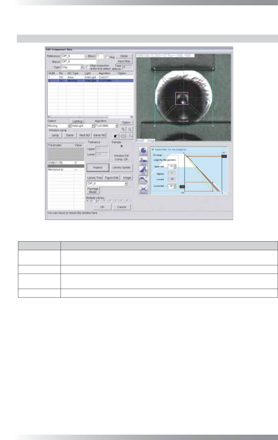
V- 41 Programming Manual Part V Inspection Data 4.2.2 Each Inspection Item Setting Press fi ve buttons in the lower right side of Figure 4-1 to display the setting window corresponding to each inspection item. Each button…
V-40
Programming Manual
Part V Inspection Data
4.2 Settings
4.2.1 Parameter of FUJIYAMA
Figure 4-2 Parameter of FUJIYAMA
Parameter Description
Lighting
Select a lighting that inspection targets are visually clear.
The selected lighting in this fi eld does not infl uence to the inspection result.
Algorithm Select FUJIYAMA.
Shift[V1-V8]
Enter the appropriate vector. Any value from V1 to V8 is available.
Select the vector according to the Memorize to fi eld of the Adjust window.
Memorize to -
Table 4-2 Parameter of FUJIYAMA
V-41
Programming Manual
Part V Inspection Data
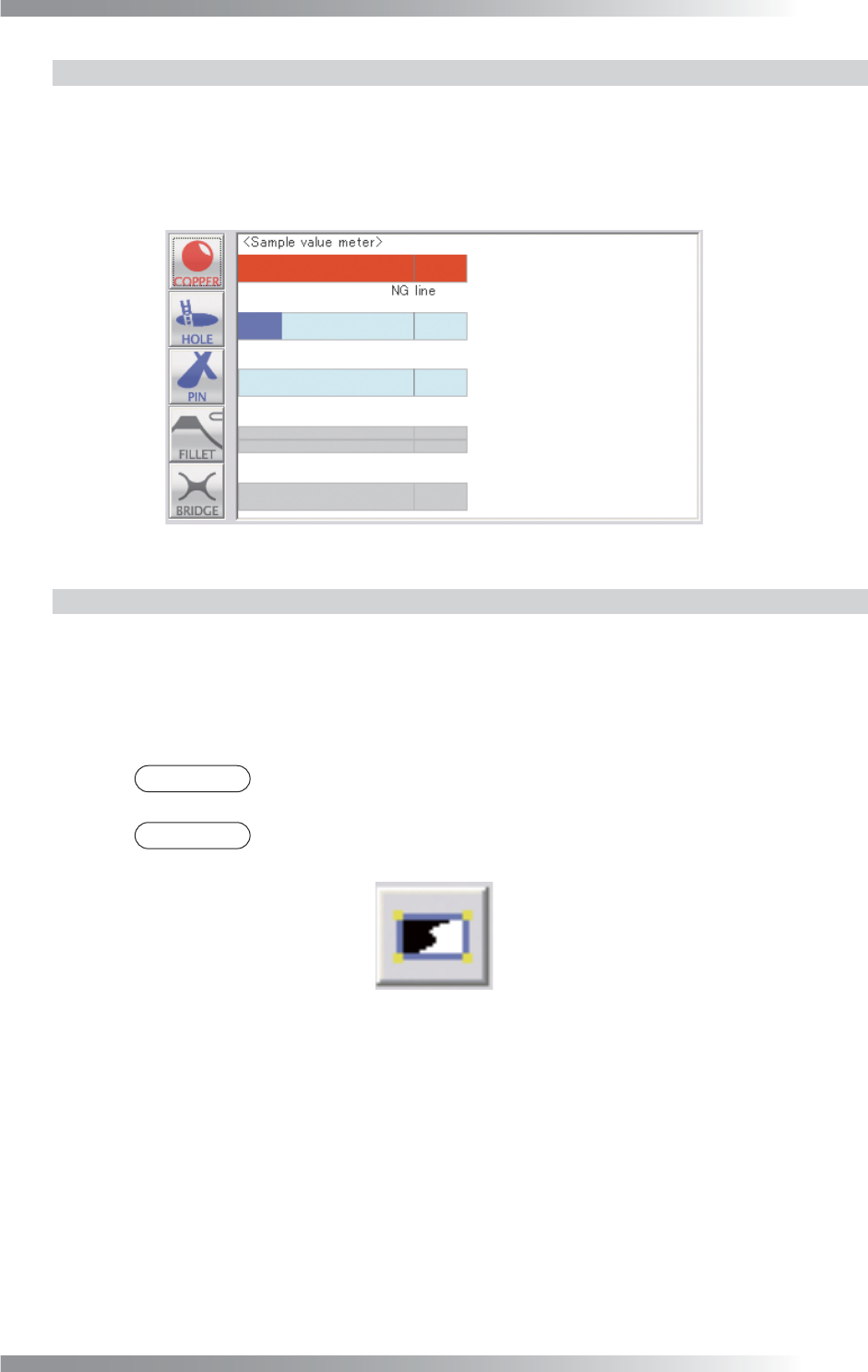
4.2.2 Each Inspection Item Setting
Press fi ve buttons in the lower right side of Figure 4-1 to display the setting window corresponding to
each inspection item. Each button color shows inspection result of each inspection item.
Blue refers OK, red refers NG, and gray refers no judgement.
If no buttons are pressed, the dialog shown in Figure 4-3 appears.
The bar graph below shows comparison of the detected value and each inspectionʼs NG value.
Figure 4-3 Each Inspection Item Setting
4.2.3 Setting Procedure of FUJIYAMA
Step1: Select FUJIYAMA from the Algorithm drop-down list.
Step2: Select a lighting that inspection targets are visually clear from the Lighting drop-down list
to adjust inspection window size.
NOTE
The inspection processing of FUJIYAMA is using the special lighting. The selected
lighting in this fi eld does not infl uence to the inspection result.
NOTE
Press black-white button in the upper side of Sample to switch between selected
lighting image and used lighting image.
Figure 4-4 Switching between the images
Step3: Adjust inspection window size to surround the pad.
Step4: Press each inspection item button to set parameters. For details, refer to Part V 4.3 Setting
of Copper Inspection, Part V 4.4 Setting of Hole Inspection, Part V 4.5 Setting of
Straight Pin Inspection, Part V 4.6 Setting of Clinch Pin Inspection, Part V 4.7 Setting
of Fillet Inspection, Part V 4.8 Setting of Bridge Inspection.
Step5: After all the settings are completed, press Inspect. Make sure that the inspection is
completed properly.
V-42
Programming Manual
Part V Inspection Data
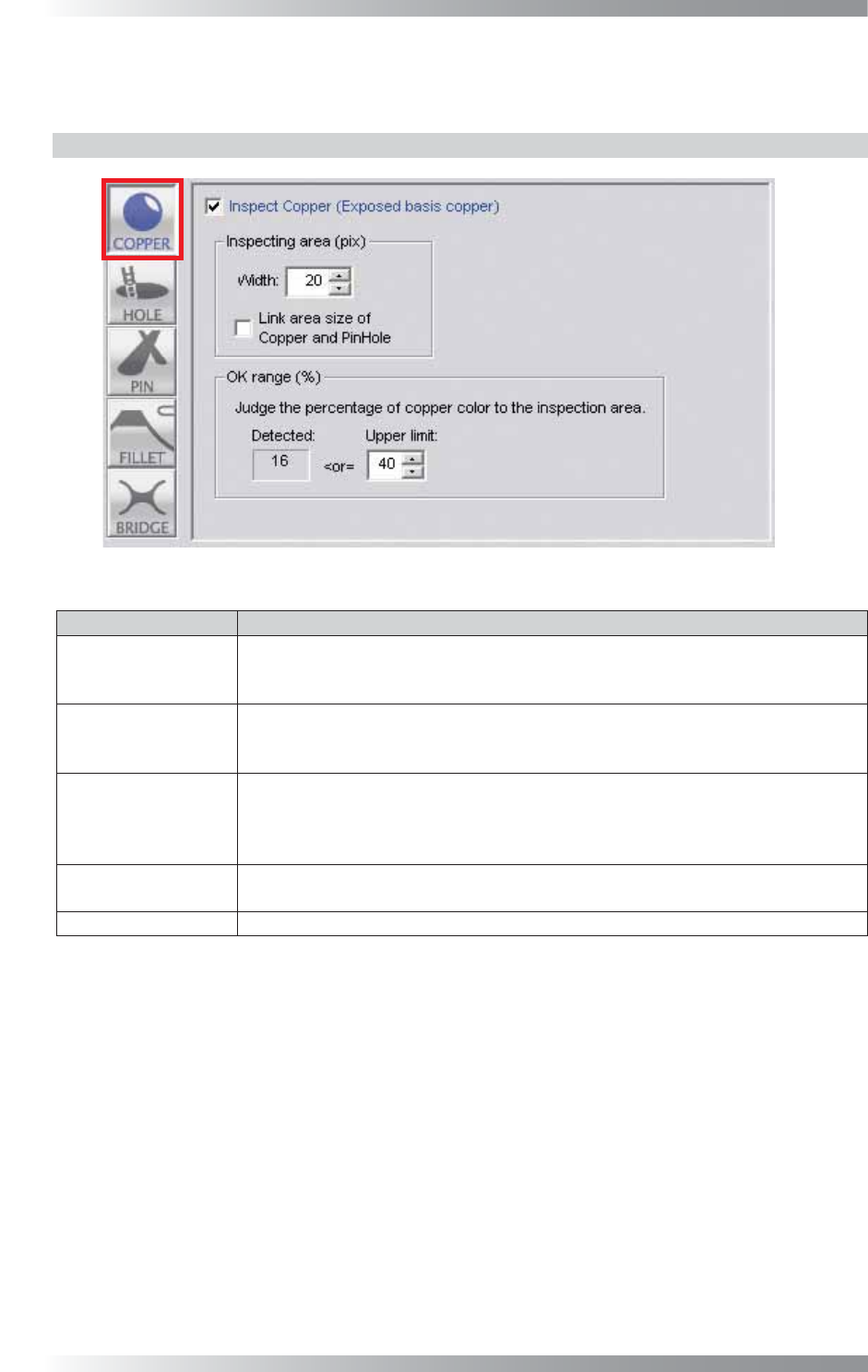
4.3 Copper Inspection Setting
Copper inspection detects an exposed copper on a pad.
4.3.1 Parameter of Copper Inspection
Figure 4-5 Copper Inspection Setting
Parameter Description
Inspect Copper
To activate Copper inspection, check Inspect Copper.
To disable copper inspection, Un-check Inspect Copper.
The button color is displayed in gray.
Width
The inspection area is specifi ed by width (pixel value) from the green circle.
The inspection area is in the green circle except the area netted.
Enter the bigger value to enlarge the inspection area.
Link area size of
Copper and PinHole
The inspection area size of Copper and Pin Hole are interlocked.
Width of Copper and Width of Pin Hole become same value.
The inspection area indicated by netting on the window of Copper becomes the
inspection area of Pin Hole.
Detected
Displays yellow dots which show a percentage of a copper-exposed area in an
inspection area.
Upper limit
Set the upper limit of the OK range.
Table 4-3 Parameter of Copper Inspection