Programming_mail.pdf - 第73页
II- 29 Programming Manual Part II Inspection Data Step3: Select IC / Connector from the Type drop-down list. Figure 1-53 Auto Deployment of IC Component 3 Step4: Set Package Type , Lead Pitch , Number of Leads X , and Nu…
II-28
Programming Manual
Part II Inspection Data
1.3.2 Auto Deployment of IC Component
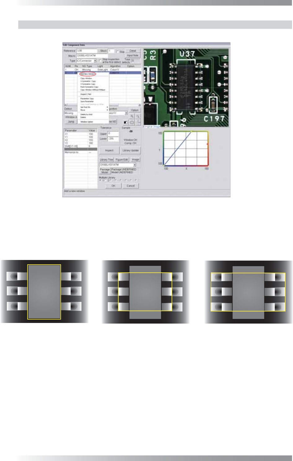
Step1: Right-click the center of CAD data. The dialog shown in Figure 1-51 appears.
Figure 1-51 Auto Deployment of IC Component 1
Step2: Select Add New Window from the right-click menu and repeat it three times to make three
inspection windows. Adjust the fi rst inspection window size to surround a body of a component.
Adjust the second inspection window size to surround leads and a body of a component.
Adjust the third inspection window size to surround pads, leads and a body of a component.
(1) Body
(2) Lead and Body
(3) Pad, Lead, and Body
Figure 1-52 Auto Deployment of IC Component 2
II-29
Programming Manual
Part II Inspection Data
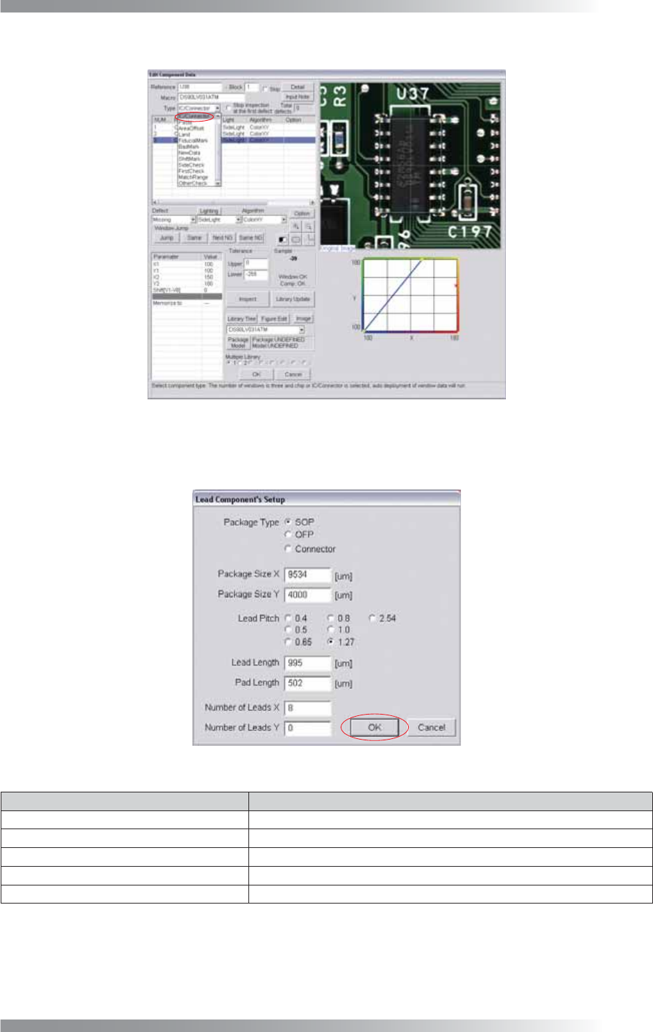
Step3: Select IC / Connector from the Type drop-down list.
Figure 1-53 Auto Deployment of IC Component 3
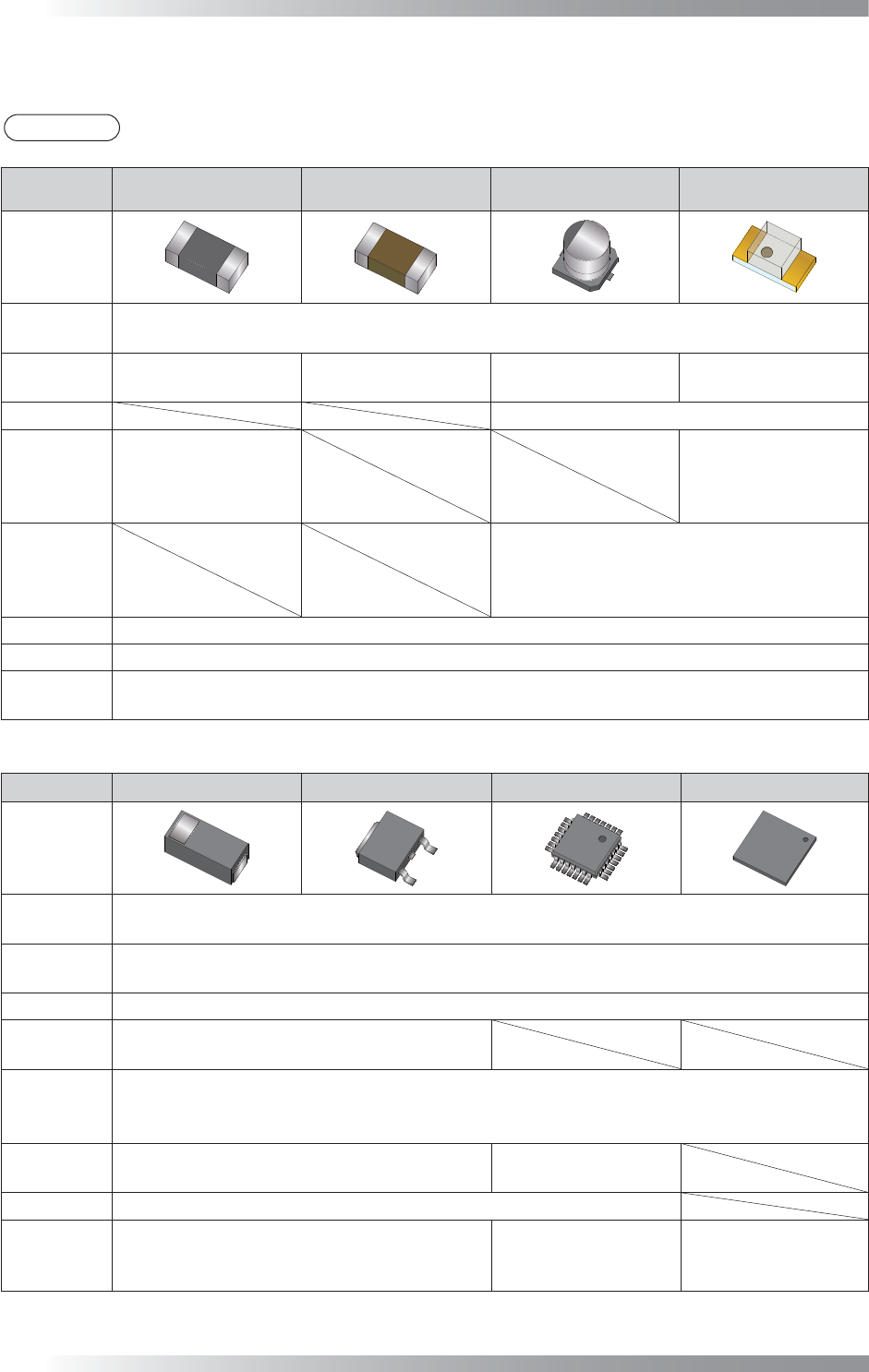
Step4: Set Package Type, Lead Pitch, Number of Leads X, and Number of Leads Y.
After all the settings are completed, press OK.
Figure 1-54 Auto Deployment of IC Component 4
Item Description
Package Type
Check SOP, QFP or Connector.
Package Size X, Package Size Y Body size is displayed.
Lead Pitch
Sets a lead pitch.
Lead Length, Pad Length
Lead length and pad length are displayed.
Number of Leads X, Number of Leads Y Enter number of leads.
Table 1-12 Description of Parameters
Step5: Inspection items are automatically made. For details of inspection data settings, refer to
Part III Inspection Algorithm.
II-30
Programming Manual
Part II Inspection Data
1.4 Major Algorithms Used for Inspections on Each Component
NOTE
According to component conditions, algorithms used may change.
NG type
Resistance Ceramic Capacitor
Aluminum
Electrolytic Capacitor
LED
Adjust
New_ASC
LTracking / WTracking
Missing
Average
Black/White
ColorXY
AreaColor
Average
Black/White
ColorXY
AreaColor
Polarity Diagonally
Reverse
Average
Black/White
Average
Black/White
ColorXY
AreaColor
Misalignment
Average
Black/White
ColorXY
AreaColor
No Solder
Black/White
Copper AreaColor
Lifted Lead
Lifted Chip
Black/White
AS_AV_LeadLength
Table 1-13 Major Algorithms Used for Inspections on Each Components1
NG type Diode Transistor SOP/QFP BGA
Adjust
New_ASC
LTracking / WTracking
Missing
Average
Black/White
Polarity Diagonally
Reverse
Average
Black/White
Misalignment
Average
Range
Black/White
No Solder
Black/White
Black/White
IC_Solder3
Copper AreaColor
Lifted Lead
Lifted Chip
Black/White
AS_AV_LeadLength
Black/White
AS_AV_LeadLength
IC_Solder3
Table 1-14 Major Algorithms Used for Inspections on Each Component 2