sh030051g.pdf - 第105页
3 - 50 3. SIGNALS AND WI RING 3.11.3 Wiring diagrams (HF-MP serie s HF-KP series servo motor) POINT For HF-SP series HC-RP se ries HC-UP series HC-LP serie s servo motors, refer to section 3.10.2 (2). (1) When cable leng…
3 - 49
3. SIGNALS AND WIRING
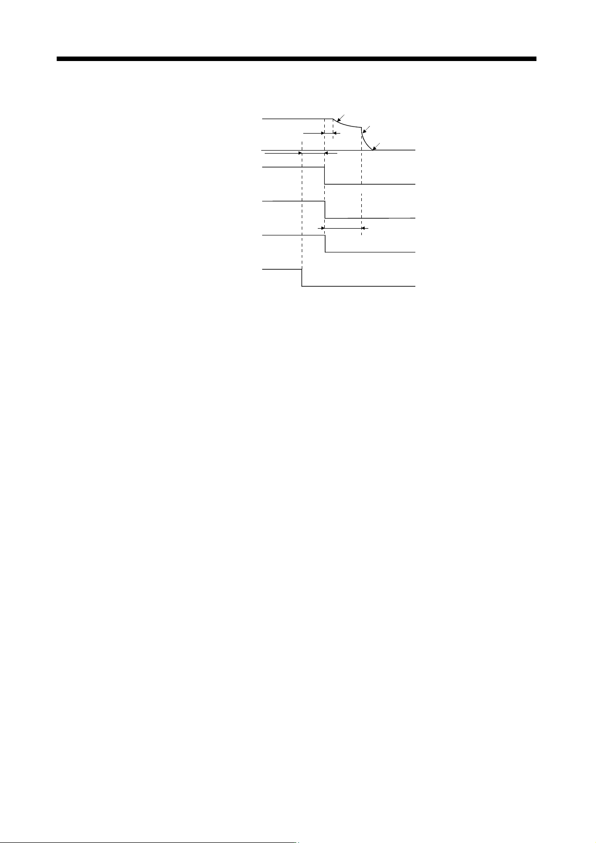
(5) Only main circuit power supply off (control circuit power supply remains on)
Servo motor speed
Base circuit
Electromagnetic
brake interlock
(MBR)
Alarm
Main circuit power
supply
Dynamic brake
Dynamic brake
Electromagnetic brake
Electromagnetic brake
Electromagnetic brake
operation delay time
(Note 2)
(10ms)
(Note 1)
15ms or more
ON
OFF
ON
OFF
No
Yes
(Note 3)
ON
OFF
(ON)
(OFF)
Note 1. Changes with the operating status.
2. When the main circuit power supply is off in a motor stop status, the main circuit off warning (E9) occurs
and the alarm (ALM) does not turn off.
3. ON: Electromagnetic brake is not activated.
OFF: Electromagnetic brake is activated.
3 - 50
3. SIGNALS AND WIRING
3.11.3 Wiring diagrams (HF-MP series
HF-KP series servo motor)
POINT
For HF-SP series HC-RP series HC-UP series HC-LP series servo motors,
refer to section 3.10.2 (2).
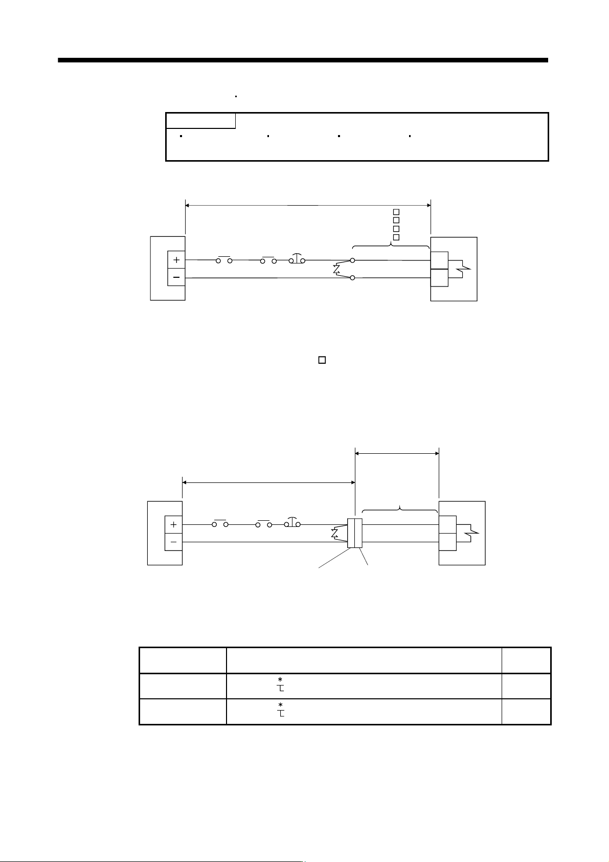
(1) When cable length is 10m or less
AWG20
AWG20
MR-BKS1CBL M-A1-L
MR-BKS1CBL M-A2-L
MR-BKS1CBL M-A1-H
MR-BKS1CBL M-A2-H
(Note 1)
B1
B2
24VDC power
supply for
electromagnetic
brake
Servo motor
10m or less
(Note2)
Electromagnetic
brake (MBR)
Forced stop
(EM1)
Trouble
(ALM)
Note 1. Connect a surge absorber as close to the servo motor as possible.
2. There is no polarity in electromagnetic brake terminals (B1 and B2).
When fabricating the motor brake cable MR-BKS1CBL-
M-H, refer to section 11.1.4.
(2) When cable length exceeds 10m
When the cable length exceeds 10m, fabricate an extension cable as shown below on the customer side. In
this case, the motor brake cable should be within 2m long.
Refer to section 11.8 for the wire used for the extension cable.
(Note 2)
a) Relay connector for
extension cable
(Note 2)
b) Relay connector for motor
brake cable
AWG20
AWG20
MR-BKS1CBL2M-A1-L
MR-BKS1CBL2M-A2-L
MR-BKS1CBL2M-A1-H
MR-BKS1CBL2M-A2-H
MR-BKS2CBL03M-A1-L
MR-BKS2CBL03M-A2-L
B1
B2
24VDC power
supply for
electromagnetic
brake
50m or less
Extension cable (To be fabricated)
(Note 1)
2m or less
Servo motor
(Note 3)
Electromagnetic
brake (MBR)
Forced stop
(EM1)
Trouble
(ALM)
Note 1. Connect a surge absorber as close to the servo motor as possible.
2. Use of the following connectors is recommended when ingress protection (IP65) is necessary.
Relay connector Description
Protective
structure
a) Relay connector for
extension cable
CM10-CR2P-
(DDK)
Wire size: S, M, L
IP65
b) Relay connector for
motor brake cable
CM10-SP2S-
(DDK)
Wire size: S, M, L
IP65
3. There is no polarity in electromagnetic brake terminals (B1 and B2).
3 - 51
3. SIGNALS AND WIRING
3.12 Grounding
WARNING
Ground the servo amplifier and servo motor securely.
To prevent an electric shock, always connect the protective earth (PE) terminal
(terminal marked
) of the servo amplifier with the protective earth (PE) of the
control box.
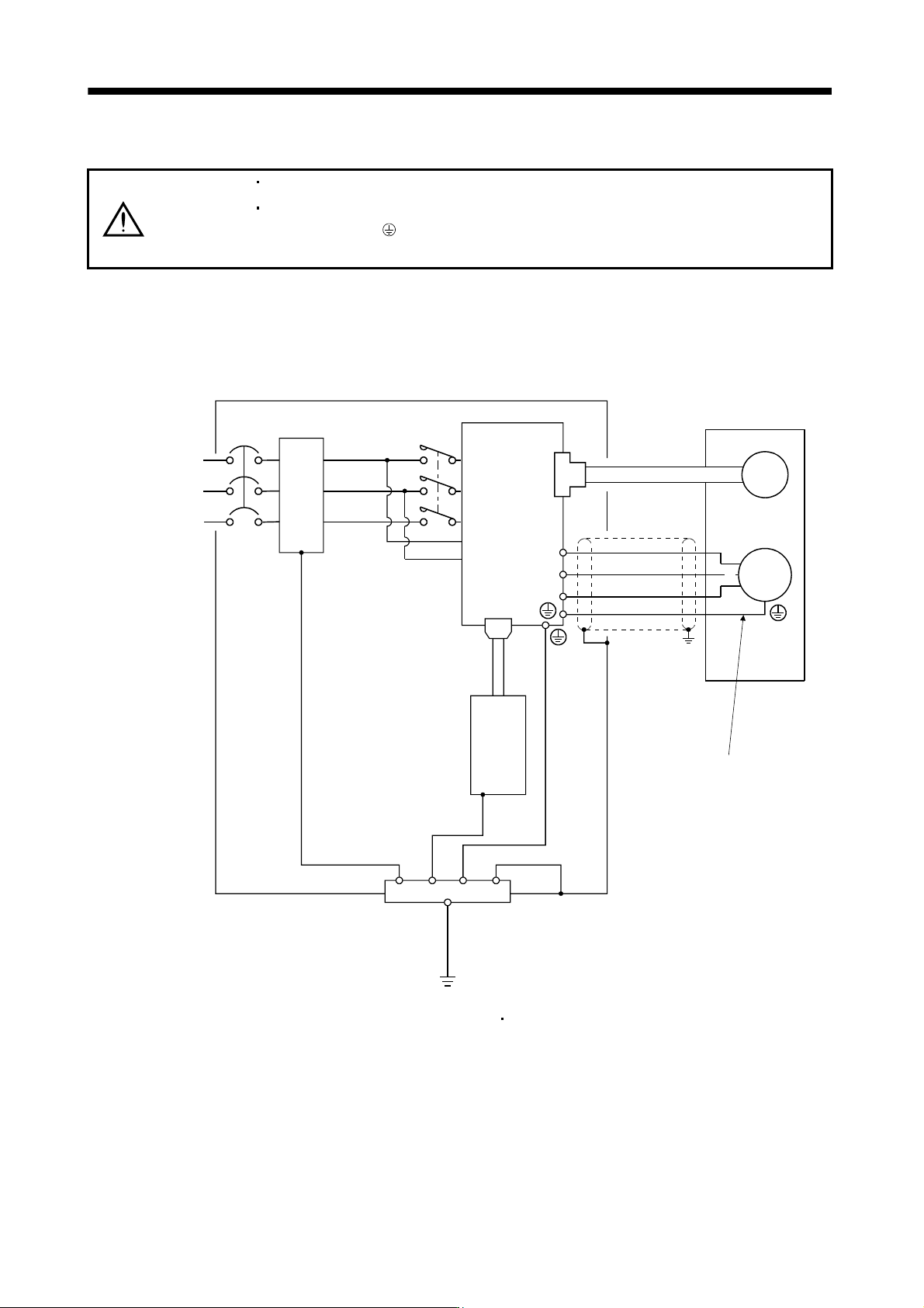
The servo amplifier switches the power transistor on-off to supply power to the servo motor. Depending on the
wiring and ground cable routing, the servo amplifier may be affected by the switching noise (due to di/dt and
dv/dt) of the transistor. To prevent such a fault, refer to the following diagram and always ground.
To conform to the EMC Directive, refer to the EMC Installation Guidelines (IB(NA)67310).
L
1
L2
L
3
L11
L21
CN1A
NFB
MC
CN2
U
V
W
M
U
V
W
Control box
Servo amplifier
Line filter
Protective earth(PE)
Outer
box
Servo motor
Encoder
(Note)
Power supply
Servo system
controller
Ensure to connect it to PE
terminal of the servo amplifier.
Do not connect it directly
to the protective earth of
the control panel.
Note. For 1-phase 200V to 230VAC, connect the power supply to L1 L2 and leave L3 open.
There is no L
3 for 1-phase 100 to 120VAC power supply. Refer to section 1.3 for the power supply specification.