sh030051g.pdf - 第247页
11 - 42 11. OPTIONS AND AUXILI ARY EQUIPMENT (5) Crimping terminals for P and N terminals of servo amplifier (a) Recommended crimping terminals POINT Always use recommended crimpi ng terminals or equivalent since some cr…
11 - 41
11. OPTIONS AND AUXILIARY EQUIPMENT
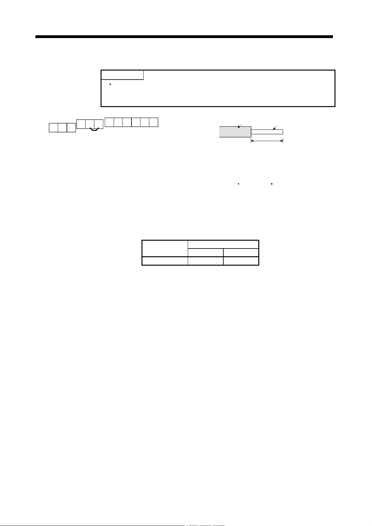
2) Control circuit terminal
POINT
Undertightening can cause a cable disconnection or malfunction.
Overtightening can cause a short circuit or malfunction due to damage to the
screw or the brake unit.
A
RES
PC
B
SD
BUE
C
MSG
SD
MSG
SD SD
Jumper
Terminal block
6mm
Sheath
Core
Wire the stripped cable after twisting to prevent the cable
from becoming loose. In addition, do not solder it.
Screw size: M3
Tightening torque: 0.5N
m to 0.6N m
Wire size: 0.3mm
2
to 0.75 mm
2
Screw driver: Small flat-blade screwdriver
(Tip thickness: 0.4mm/Tip width 2.5mm)
(b) Cables for connecting the servo amplifier and a distribution terminal block when connecting two sets of
the brake unit
Brake unit
Wire size
HIV wire [mm
2
]AWG
FR-BU2-15K 8 8
11 - 42
11. OPTIONS AND AUXILIARY EQUIPMENT
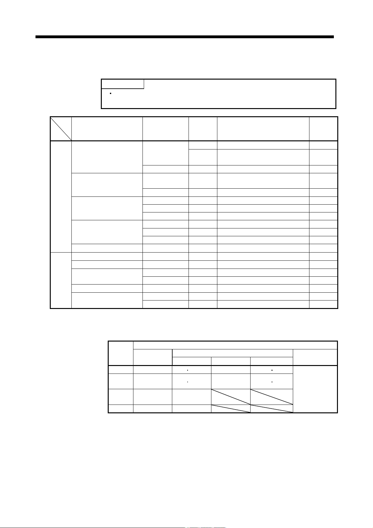
(5) Crimping terminals for P and N terminals of servo amplifier
(a) Recommended crimping terminals
POINT
Always use recommended crimping terminals or equivalent since some
crimping terminals cannot be installed depending on the size.
Servo amplifier Brake unit
Number of
connected
units
Crimping terminal (Manufacturer)
(Note 1)
Applicable
tool
200V MR-J3-500B FR-BU2-15K 1 FVD5.5-S4(Japan Solderless Terminal) c
class 2 8-4NS(Japan Solderless Terminal)
(Note 2)
d
FR-BU2-30K 1 FVD5.5-S4(Japan Solderless Terminal) c
MR-J3-700B FR-BU2-15K 2 8-4NS(Japan Solderless Terminal)
(Note 2)
d
FR-BU2-30K 1 FVD5.5-S4(Japan Solderless Terminal) c
MR-J3-11KB FR-BU2-15K 2 FVD8-6(Japan Solderless Terminal) a
FR-BU2-30K 1 FVD5.5-6(Japan Solderless Terminal) c
FR-BU2-55K 1 FVD14-6(Japan Solderless Terminal) b
MR-J3-15KB FR-BU2-15K 2 FVD8-6(Japan Solderless Terminal) a
FR-BU2-30K 1 FVD5.5-6(Japan Solderless Terminal) c
FR-BU2-55K 1 FVD14-6(Japan Solderless Terminal) b
MR-J3-22KB FR-BU2-55K 1 FVD14-8(Japan Solderless Terminal) b
400V MR-J3-500B4 FR-BU2-H30K 1 FVD5.5-S4(Japan Solderless Terminal) c
class MR-J3-700B4 FR-BU2-H30K 1 FVD5.5-S4(Japan Solderless Terminal) c
MR-J3-11KB4 FR-BU2-H30K 1 FVD5.5-6(Japan Solderless Terminal) c
FR-BU2-H55K 1 FVD5.5-6(Japan Solderless Terminal) c
MR-J3-15KB4 FR-BU2-H55K 1 FVD5.5-6(Japan Solderless Terminal) c
MR-J3-22KB4 FR-BU2-H55K 1 FVD5.5-8(Japan Solderless Terminal) c
FR-BU2-H75K 1 FVD14-8(Japan Solderless Terminal) b
Note 1. Symbols in the applicable tool field indicate applicable tools in (5)(b) of this section.
2. Coat the crimping part with an insulation tube.
(b) Applicable tool
Symbol
Servo amplifier side crimping terminals
Crimping
terminal
Applicable tool
Manufacturer
Body Head Dice
a FVD8-6 YF-1 E-4 YNE-38 DH-111 DH121
Japan Solderless
Terminal
b
FVD14-6
FVD14-8
YF-1 E-4 YNE-38 DH-112 DH122
c
FDV5.5-S4
FDV5.5-6
YNT-1210S
d 8-4NS YHT-8S
11 - 43
11. OPTIONS AND AUXILIARY EQUIPMENT
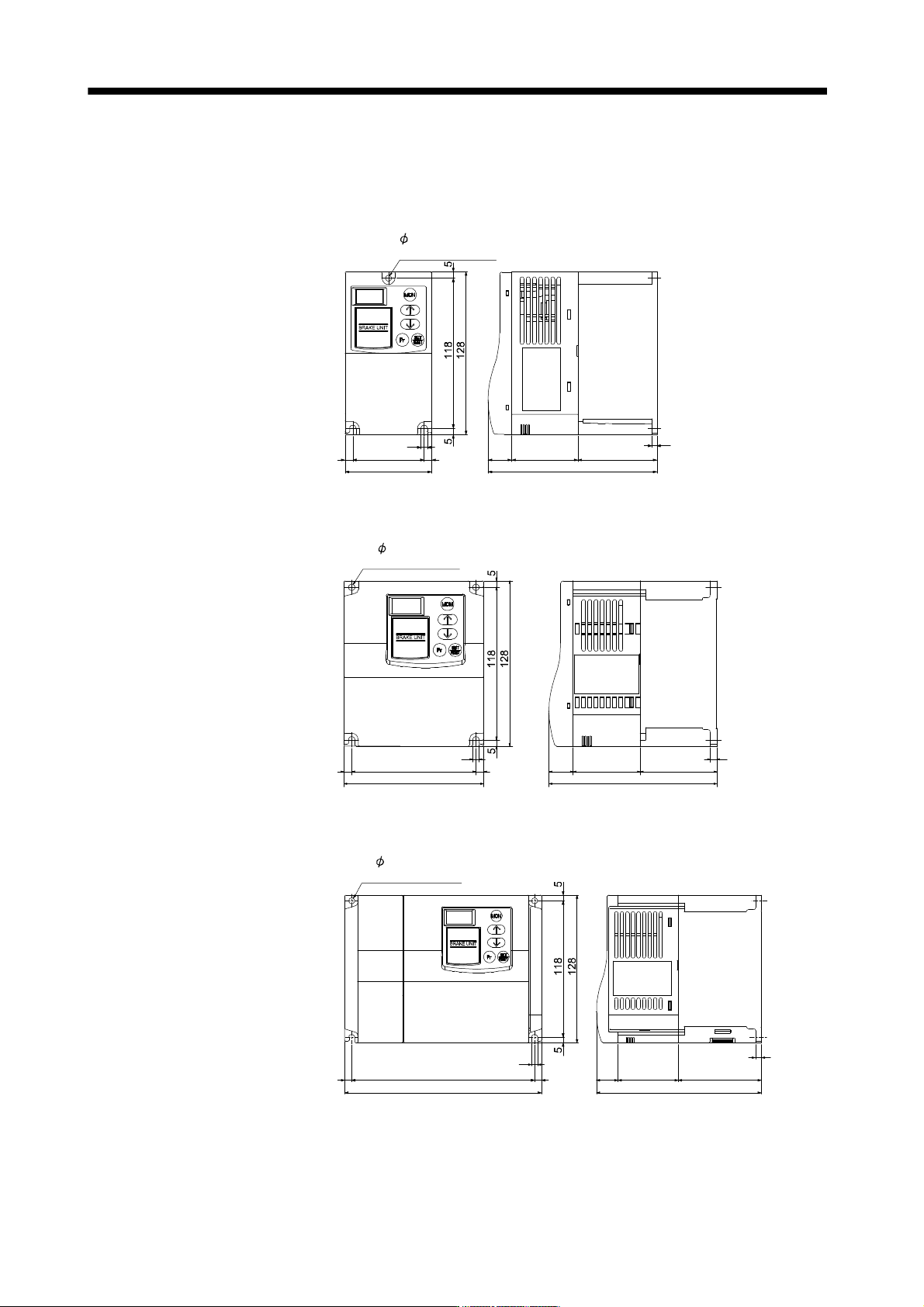
11.3.4 Outline dimension drawings
(1) FR-BU2- (H) brake unit
[Unit: mm]
FR-BU2-15K
Rating
plate
5 hole
(Screw size: M4)
68
6 56 6
5
18.5
52 62
4
132.5
FR-BU2-30K
FR-BU2-H30K
129.5
5
59
18.5
Rating
plate
52
2- 5 hole
(Screw size: M4)
5
108
6 6
96
FR-BU2-55K
FR-BU2-H55K, H75K
18.5
Rating
plate
52 72
5
142.5
5
61586
170
2- 5 hole
(Screw size: M4)