sh030051g.pdf - 第304页
13 - 3 13. SERVO AMPLIFIERS WI TH A LARGE CAPACITY ( 30k TO 55kW ) Model position contro l Model spe ed control L L L L Current control Actual speed control Actual position contro l OHS2 Optional battery (For absolute po…
13 - 2
13. SERVO AMPLIFIERS WITH A LARGE CAPACITY
(
30k TO 55kW
)
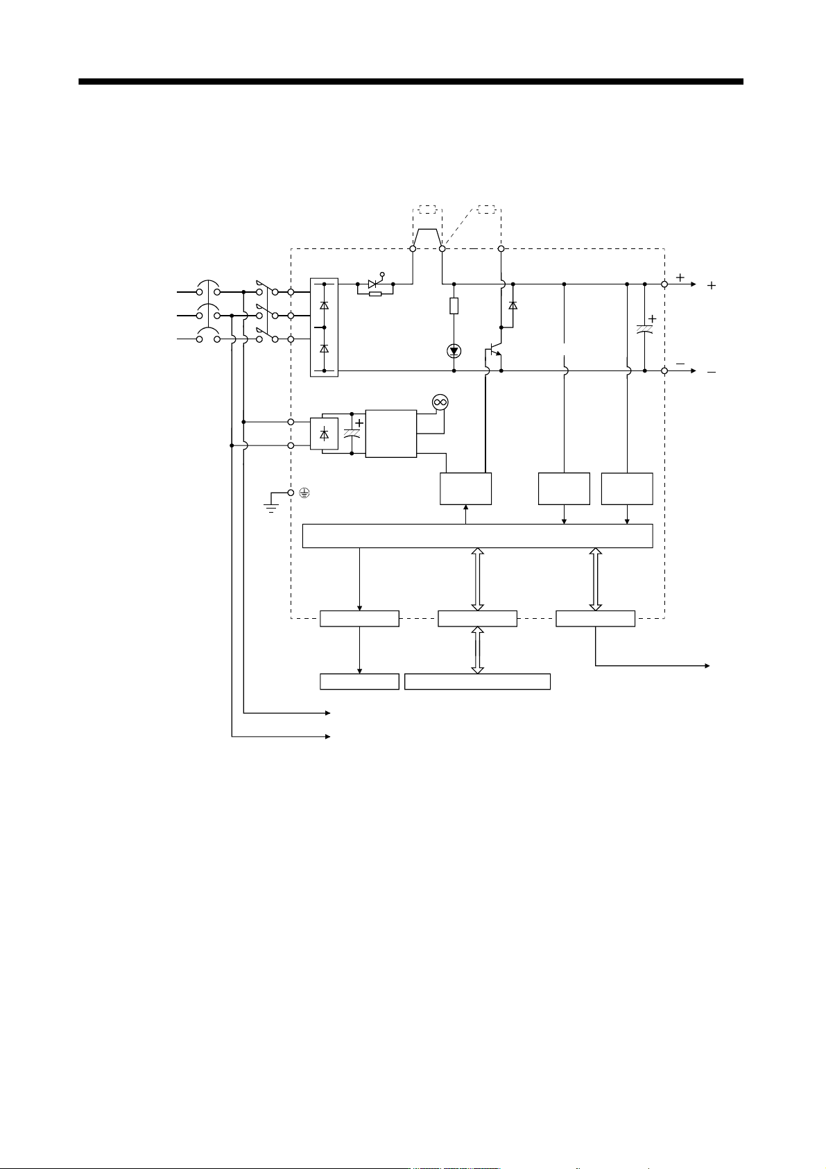
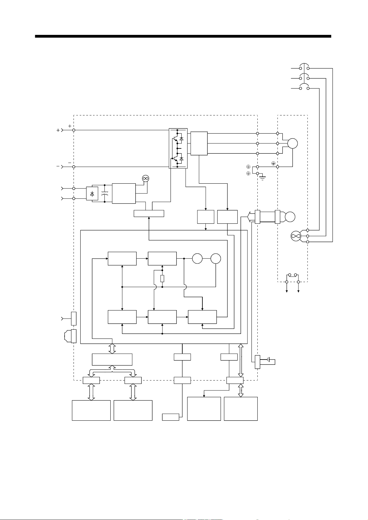
13.1.1 Function block diagram
The function block diagram of this servo is shown below.
L
L
11
L
21
L1
L
2
L3
P
1
P
2
C
L
11
L21
L
L
L
Power
supply
Control
power
supply
Base
amplifier
MC
CN1
I/F
CHARGE
lamp
Converter
NFB
Cooling fan
CPU
Trouble, warning, forced stop
CN40
Converter unit
protection coordination
CN40
Power factor
improving DC
CNP1
MC drive
Regenerative
option
Regenerative
TR
Diode
stack
Thyristor
Current
detection
Voltage
detection
13 - 3
13. SERVO AMPLIFIERS WITH A LARGE CAPACITY
(
30k TO 55kW
)
Model position
control
Model speed
control
L
L
L
L
Current
control
Actual speed
control
Actual position
control
OHS2
Optional battery
(For absolute position detection
system)
Termination
connector
MR-J3-TM
(Option)
CN40
BU
BV
BW
U
V
W
Over
current
Control
power
supply
Current
detector
NFB
Power
supply
(Note)
CN40ACN40B
CN5
USB
USB
Personal
computer
CN4
MR-J3BAT
Controller
or
drive unit
Drive unit
or
cap
CN1A CN1B
CN3
D/A
Analog monitor
(2 channel)
Digital I/O
control
Servo motor
Drive unit
L
11
L
11
L
21
L
21
Cooling fan
Base amplifier
U
V
W
M
CN2
Servo motor
thermal
OHS1
Current
detection
Virtual
encoder
Position command
input
Model position Model speed
Virtual
motor
I/F
Control
Encoder
Model torque
Cooling fan
Note. Refer to section 13.3.6 for the power supply specification of the servo motor cooling fan.
13 - 4
13. SERVO AMPLIFIERS WITH A LARGE CAPACITY
(
30k TO 55kW
)
13.1.2 Packing list
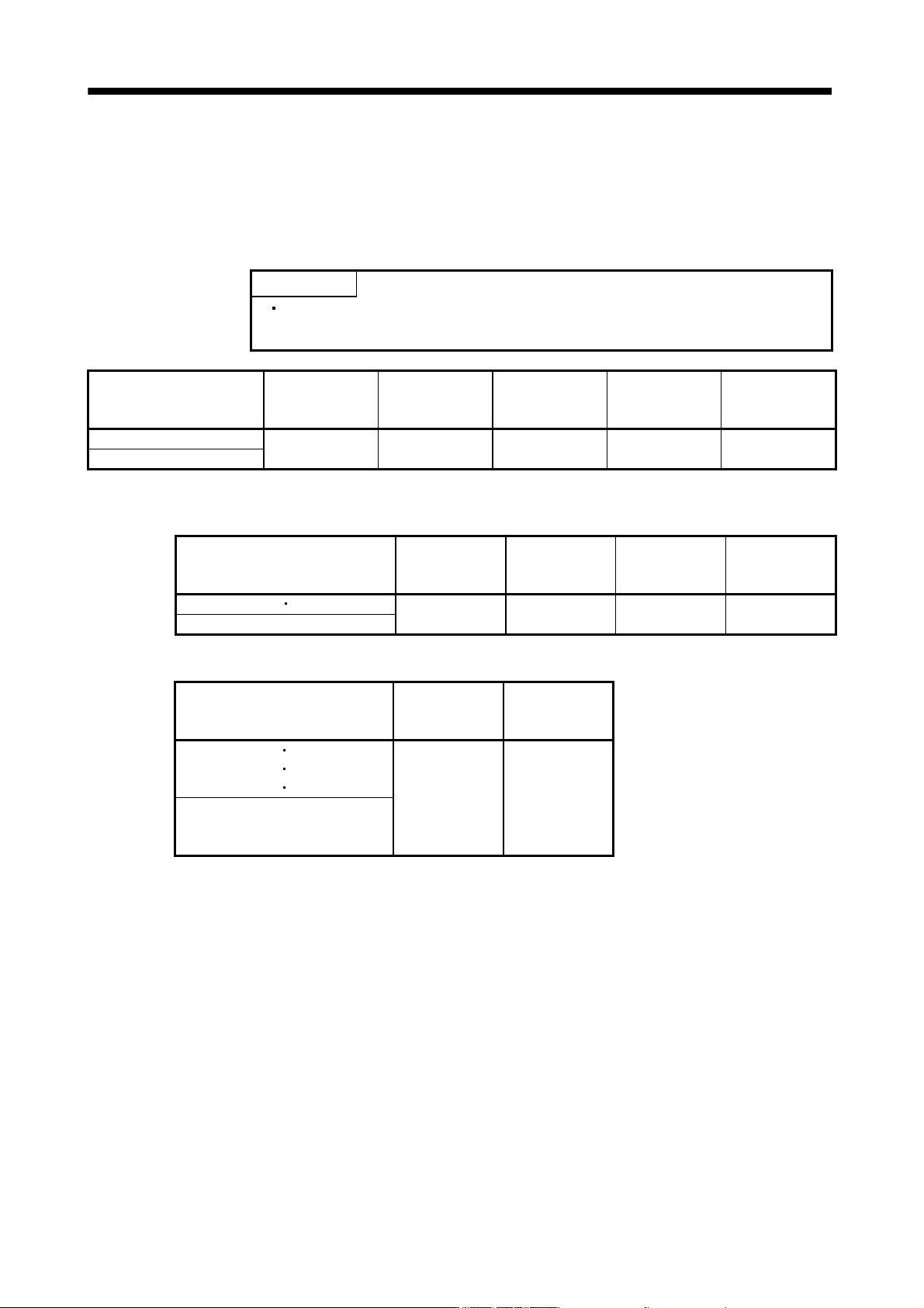
Unpack the product and check the rating plate to see if the converter unit, drive unit and servo motor are as you
ordered.
(1) Converter unit
POINT
Regenerative resistor and power factor improving DC reactors are option.
Purchase them separately if required. (Section 13.9.2, 13.9.6)
Model
Converter unit
[units]
Eyebolt
[pcs.]
Magnetic contactor
wiring connector
[pcs.] (Note)
Digital I/O connector
[pcs.]
To use the AC
servo safely
[manuals]
MR-J3-CR55K
1 2 1 1 1
MR-J3-CR55K4
Note. Magnetic contactor control connector is mounted to CNP1 of the converter unit before shipping.
(2) Drive unit
Model
Drive unit
[units]
Connection
conductor
[pcs.]
Eyebolt
[pcs.]
To use the AC
servo safely
[manuals]
MR-J3-DU30KB MR-J3-DU37KB
1 2 2 1
MR-J3-DU30KB4 to MR-J3-DU55KB4
(3) Servo motor
Model
Servo motor
[units]
To use the AC
servo safely
[manuals]
HA-LP30K1 HA-LP37K1
HA-LP30K1M
HA-LP37K1M
HA-LP30K2
HA-LP37K2
1 1
HA-LP25K14 to HA-LP37K14
HA-LP30K1M4 to HA-LP50K1M4
HA-LP30K24 to HA-LP55K24