sh030051g.pdf - 第221页
11 - 16 11. OPTIONS AND AUXILI ARY EQUIPMENT (5) MR-J3BTCBL03M This cable is a battery connection c able . Use this cable to retain the current position even if the detector cable is disconnected from the servo amplifier…
11 - 15
11. OPTIONS AND AUXILIARY EQUIPMENT
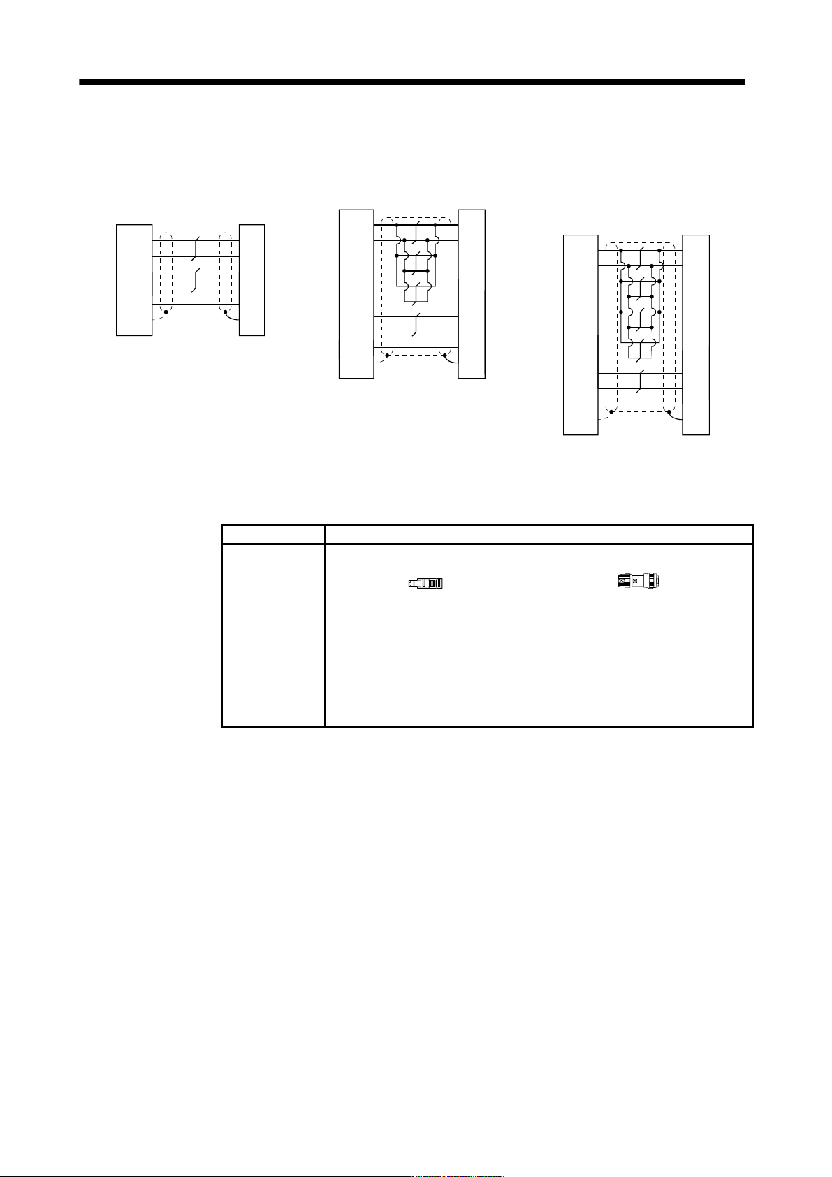
(b) Internal wiring diagram
P5
LG
1
2
MR
MRR
3
4
4
8
9
SD
1
2
5
10
LG
MR
MRR
SHD
P5
BAT
BAT
Servo amplifier
side connector
Encoder side
connector
Plate
MR-J3ENSCBL10M-L/H
MR-J3ENSCBL5M-L/H
MR-J3ENSCBL2M-L/H
Servo amplifier
side connector
Encoder side
connector
Plate
P5
LG
1
2
MR
MRR
3
4
4
8
9
SD
1
2
5
10
LG
MR
MRR
SHD
P5
BATBAT
MR-J3ENSCBL30M-L
MR-J3ENSCBL20M-L
Servo amplifier
side connector
Encoder side
connector
Plate
P5
LG
1
2
MR
MRR
3
4
4
8
9
SD
1
2
5
10
LG
MR
MRR
SHD
P5
BATBAT
MR-J3ENSCBL50M-H
MR-J3ENSCBL40M-H
MR
-J3ENSCBL30M-H
MR-J3ENSCBL20M-H
(c) When fabricating the encoder cable
When fabricating the cable, prepare the following parts and tool, and fabricate it according to the wiring
diagram in (b). Refer to section 11.8 for the specifications of the used cable.
Parts/Tool Description
Connector set MR- J3SCNS (Option)
Servo amplifier side connector
Receptacle: 36210-0100PL
Shell kit: 536310-3200-008
(3M)
Or
Connector set: 54599-1019
(Molex)
Encoder side connector
Straight plug: CM10-SP10S-M
Socket contact: CM10-#22SC(S1)-100
Applicable wire size: AWG20 or less
Recommended tightening jig: 357J-51456T
(DDK)
11 - 16
11. OPTIONS AND AUXILIARY EQUIPMENT
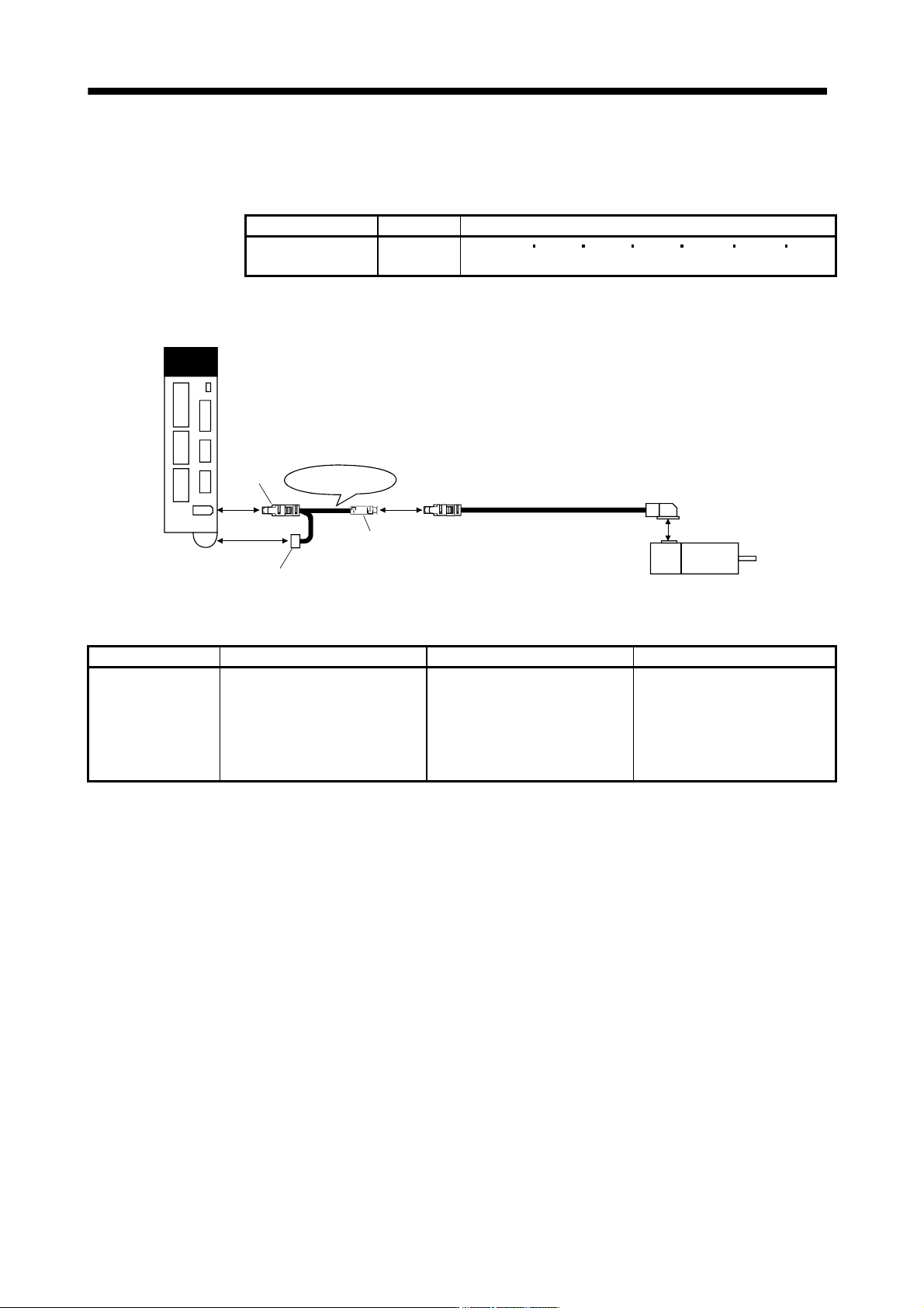
(5) MR-J3BTCBL03M
This cable is a battery connection cable. Use this cable to retain the current position even if the detector
cable is disconnected from the servo amplifier.
Cable model Cable length Application
MR-J3BTCBL03M 0.3m For HF-MP HF-KP HF-SP HA-LP HC-RP HC-UP HC-LP
servo motor
(a) Connection of servo amplifier and servo motor
Servo amplifier
1)
2)
Servo motor
(Note)
Encoder cable
MR-J3BTCBL03M
3)
Battery
CN2
Note. For the detector cable, refer to (1), (2), (3) and (4) of this section.
Cable model 1) For CN2 connector 2) Junction connector 3) For battery connector
MR-J3BTCBL03M Receptacle: 36210-0100PL
Shell kit: 536310-3200-008
(3M)
Or
Connector set: 54599-1019
(Molex)
Plug: 36110-3000FD
Shell kit: 36310-F200-008
(3M)
Connector: DF3-2EP-2C
Contact: DF3-EP2428PCA
(Hirose Denki)
11 - 17
11. OPTIONS AND AUXILIARY EQUIPMENT
11.1.3 Motor power supply cables
These cables are motor power supply cables for the HF-MP
HF-KP series servo motors. The numerals in the
Cable length field of the table are the symbols entered in the
part of the cable model. The cables of the
lengths with the symbols are available.
Refer to section 3.10 when wiring.
Cable model
Cable length
Protective
structure
Flex life Application
0.3m 2m 5m 10m
MR-PWS1CBL M-A1-L 2 5 10 IP65 Standard
For HF-MP
HF-KP servo motor
Load side lead
MR-PWS1CBL M-A2-L 2 5 10 IP65 Standard
For HF-MP
HF-KP servo motor
Opposite-to-load side lead
MR-PWS1CBL M-A1-H 2 5 10 IP65
Long flex
life
For HF-MP
HF-KP servo motor
Load side lead
MR-PWS1CBL M-A2-H 2 5 10 IP65
Long flex
life
For HF-MP
HF-KP servo motor
Opposite-to-load side lead
MR-PWS2CBL M-A1-L 03 IP55 Standard
For HF-MP
HF-KP servo motor
Load side lead
MR-PWS2CBL M-A2-L 03 IP55 Standard
For HF-MP
HF-KP servo motor
Opposite-to-load side lead
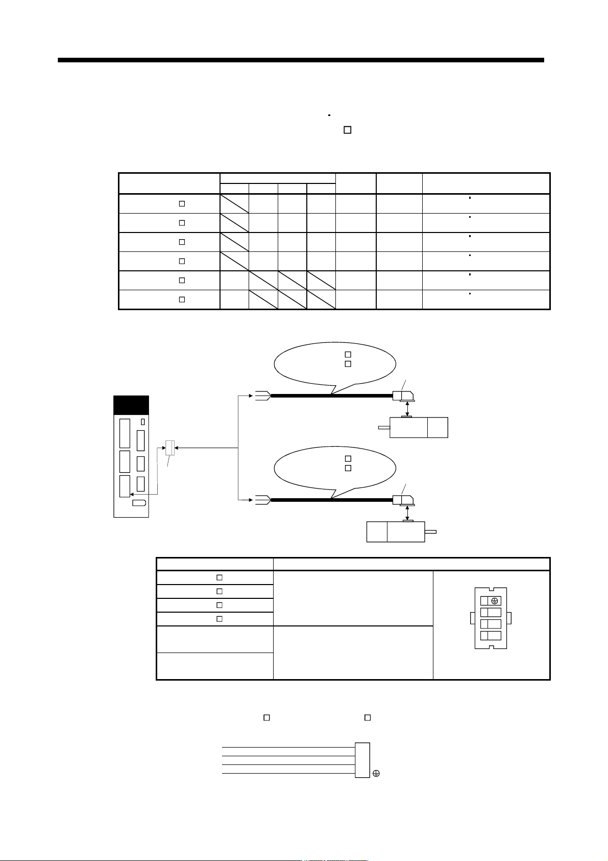
(1) Connection of servo amplifier and servo motor
Servo amplifier
1)
CNP3 connector
supplied with servo
amplifier
Servo motor
HF-MP
HF-KP
MR-PWS1CBL M-A2-L
MR-PWS1CBL M-A2-H
MR-PWS2CBL03M-A2-L
CNP3
1)
Servo motor
HF-MP
HF-KP
MR-PWS1CBL M-A1-L
MR-PWS1CBL M-A1-H
MR-PWS2CBL03M-A1-L
or
Cable model
1) For motor power supply connector
MR-PWS1CBL M-A1-L
Connector: JN4FT04SJ1-R
Hood, socket insulator
Bushing, ground nut
Contact: ST-TMH-S-C1B-100-(A534G)
Crimping tool: CT160-3-TMH5B
(Japan Aviation Electronics Industry)
U
V
W
1
2
3
4
View seen from wiring side.
Signal layout
MR-PWS1CBL M-A2-L
MR-PWS1CBL M-A1-H
MR-PWS1CBL M-A2-H
MR-PWS2CBL03M-A1-L
Connector: JN4FT04SJ2-R
Hood, socket insulator
Bushing, ground nut
Contact: ST-TMH-S-C1B-100-(A534G)
Crimping tool: CT160-3-TMH5B
(Japan Aviation Electronics Industry)
MR-PWS2CBL03M-A2-L
(2) Internal wiring diagram
AWG 19 (Red)
AWG 19 (White)
AWG 19 (Black)
AWG 19 (Green/yellow)
U
V
W
MR-PWS1CBL M-A1-H MR-PWS1CBL M-A2-H
MR-PWS2CBL03M-A1-L MR-PWS2CBL03M-A2-L
(Note)
Note. These are not shielded cables.