sh030051g.pdf - 第371页
13 - 70 13. SERVO AMPLIFIERS WI TH A LARGE CAPACITY ( 30k TO 55kW ) (b) Dynamic brake time constant The following shows necessary dynamic brake time constant for the equations (13.1). 40 35 30 25 20 15 10 5 0 200 6 00 10…
13 - 69
13. SERVO AMPLIFIERS WITH A LARGE CAPACITY
(
30k TO 55kW
)
13.8.3 Dynamic brake characteristics
(1) Dynamic brake operation
(a) Calculation of coasting distance
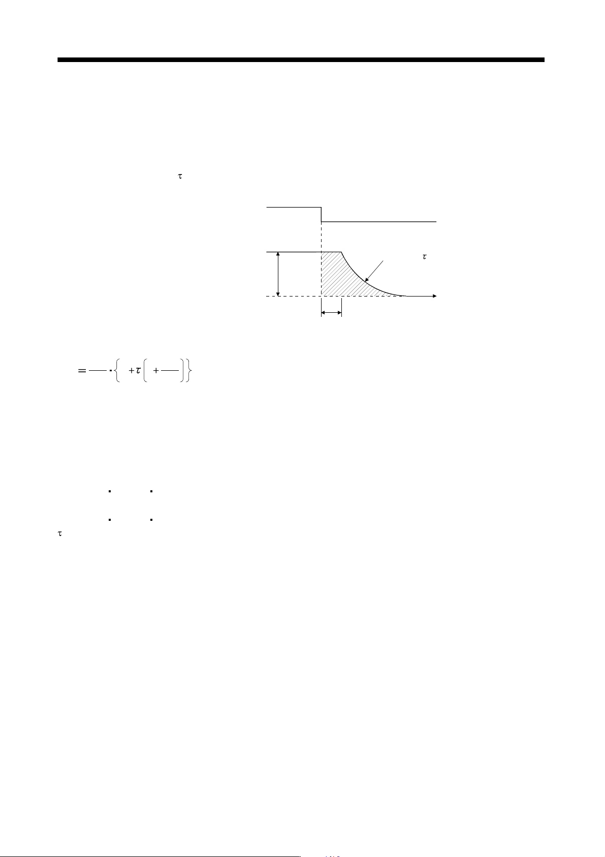
Fig. 13.2 shows the pattern in which the servo motor comes to a stop when the dynamic brake is
operated. Use Equation 13.1 to calculate an approximate coasting distance to a stop. The dynamic
brake time constant
varies with the servo motor and machine operation speeds. (Refer to (b). Please
contact us for the servo motor not indicated.)
te
Forced stop (EM1)
Machine speed
Time constant
Time
OFF
ON
V
0
Fig 13.2 Dynamic Brake Operation Diagram
60
L
max
Vo
t
e
1
JM
JL
·················································································································· (13.1)
L
max : Maximum coasting distance
·········································································································· [mm]
V
0
: Machine rapid feed rate ······························································································
[mm/min][in/min]
J
M
: Servo motor inertial moment ······················································································
[kg
cm
2
][oz in
2
]
J
L
: Load inertia moment converted into equivalent value on servo motor shaft ··············
[kg
cm
2
][oz in
2
]
: Brake time constant
·························································································································· [s]
t
e : Delay time of control section
············································································································ [s]
For 7kW or less servo, there is internal relay delay time of about 30ms. For 11k to 22kW servo, there
is delay time of about 100ms caused by a delay of the external relay and a delay of the magnetic
contactor built in the external dynamic brake.
13 - 70
13. SERVO AMPLIFIERS WITH A LARGE CAPACITY
(
30k TO 55kW
)
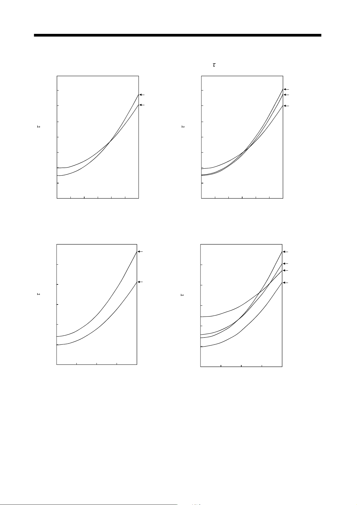
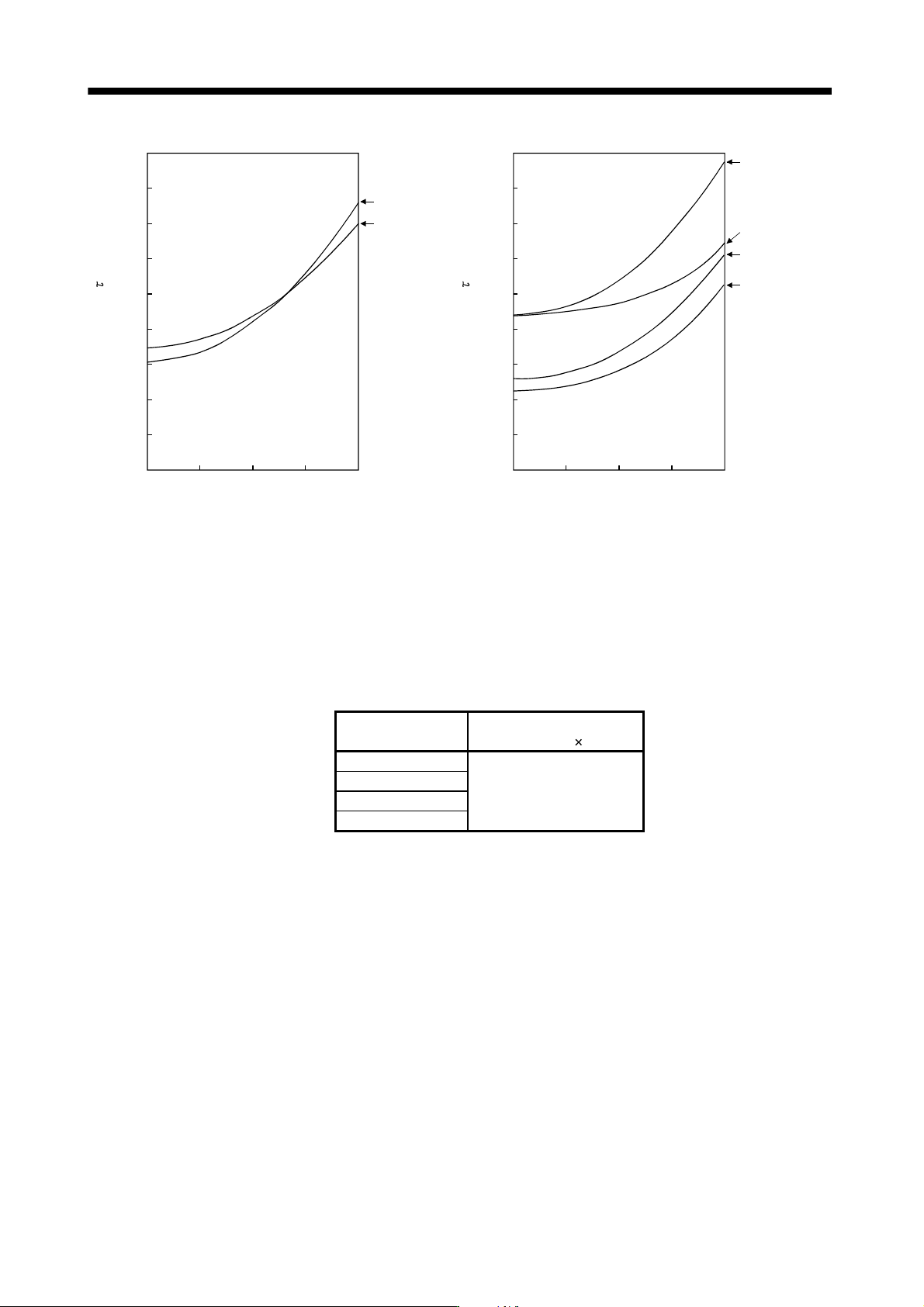
(b) Dynamic brake time constant
The following shows necessary dynamic brake time constant
for the equations (13.1).
40
35
30
25
20
15
10
5
0
200 600 100001200
Speed [r/min]
HA-LP30K1
HA-LP37K1
400 800
Time constant [ms]
40
35
30
25
20
15
10
5
0
200 600 100001200
Speed [r/min]
400 800
Time constant [ms]
HA-LP30K14
HA-LP37K14
HA-LP25K14
HA-LP1000r/min series
60
50
40
30
20
10
0
1000 150002000
HA-LP30K1M
500
HA-LP37K1M
Speed [r/min]
Time constant [ms]
60
50
40
30
20
10
0
1000 150002000
HA-LP30K1M4
500
HA-LP37K1M4
HA-LP45K1M4
HA-LP50K1M4
Speed [r/min]
Time constant [ms]
HA-LP1500r/min series
13 - 71
13. SERVO AMPLIFIERS WITH A LARGE CAPACITY
(
30k TO 55kW
)
45
40
35
30
25
20
15
10
5
0
500 1000 15000
2000
HA-LP30K2
HA-LP37K2
Speed [r/min]
Time constant [ms]
45
40
35
30
25
20
15
10
5
0
500 1000 15000
2000
HA-LP45K24
HA-LP55K24
HA-LP37K24
HA-LP30K24
Speed [r/min]
Time constant [ms]
HA-LP2000r/min series
(2) The dynamic brake at the load inertia moment
Use the dynamic brake under the load inertia moment ratio indicated in the following table. If the load inertia
moment is higher than this value, the external dynamic brake may burn. If there is a possibility that the load
inertia moment may exceed the value, contact Mitsubishi.
The values of the load inertia moment ratio in the table are the values at the maximum rotation speed of the
servo motor.
Drive unit
Load inertia moment ratio
[Multiplier (
1)]
MR-J3-DU30KB(4)
MR-J3-DU37KB(4)
10
MR-J3-DU45KB4
MR-J3-DU55KB4