sh030051g.pdf - 第197页
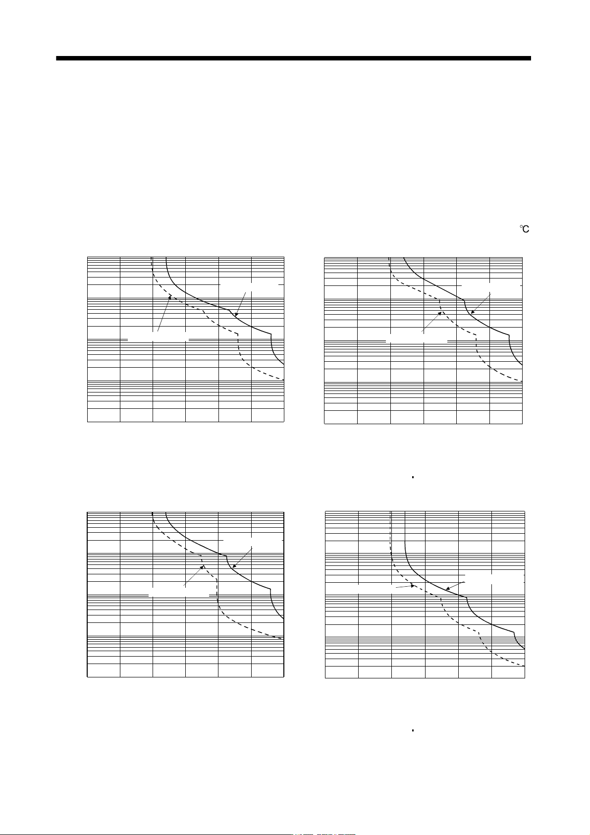
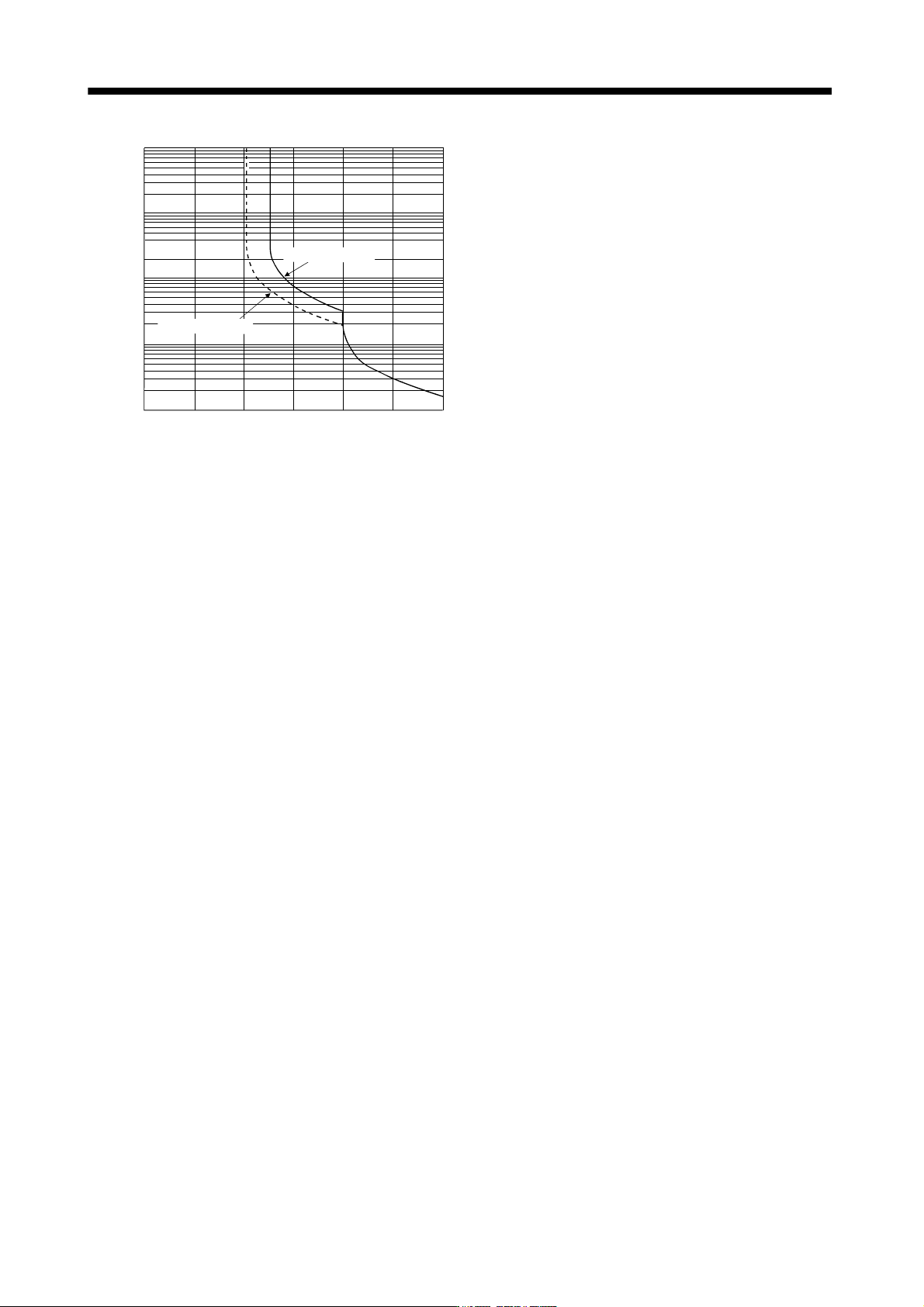
10 - 2 10. CHARACTERISTIC S 10000 1000 100 10 1 0 100 20 0 300 During operation During servo lock O p e r a t i o n t i m e [ s ] (Note) Load ratio [%] MR-J3-11KB(4 ) to MR-J3-22 KB(4) Note. If operation that generates t…
10 - 1
10. CHARACTERISTICS
10. CHARACTERISTICS
10.1 Overload protection characteristics
An electronic thermal relay is built in the servo amplifier to protect the servo motor and servo amplifier from
overloads. Overload 1 alarm (50) occurs if overload operation performed is above the electronic thermal relay
protection curve shown in any of Figs 10.1. Overload 2 alarm (51) occurs if the maximum current flew
continuously for several seconds due to machine collision, etc. Use the equipment on the left-hand side area of
the continuous or broken line in the graph.
In a machine like the one for vertical lift application where unbalanced torque will be produced, it is
recommended to use the machine so that the unbalanced torque is 70% or less of the rated torque.
When you carry out adhesion mounting of the servo amplifier, make circumference temperature into 0 to 45
,
or use it at 75% or smaller effective load ratio.
1000
100
10
1
0.1
0 50 150 200 250 300100
(Note) Load ratio [%]
Operation time[s]
During operation
During servo lock
MR-J3-10B(1)
1000
100
10
1
0.1
0 50 150 200 250 300
100
(Note) Load ratio [%]
Operation time[s]
During operation
During servo lock
MR-J3-20B(1) MR-J3-40B(1)
MR-J3-60B(4) to MR-J3-100B(4)
1000
100
10
1
0.1
0 50 150 200 250 300
100
(Note) Load ratio [%]
Operation time[s]
During operation
During servo lock
MR-J3-200B(4) to MR-J3-350B(4)
(Note) Load ratio [%]
Operation time[s]
10000
1000
100
10
1
0 50 150 200 250100 300
During operation
During servo lock
MR-J3-500B(4) MR-J3-700B(4)
10 - 2
10. CHARACTERISTICS
10000
1000
100
10
1
0 100 200 300
During operation
During servo lock
O
p
e
r
a
t
i
o
n
t
i
m
e
[
s
]
(Note) Load ratio [%]
MR-J3-11KB(4) to MR-J3-22KB(4)
Note. If operation that generates torque more than 100% of the rating is performed with an abnormally high frequency in a servo motor
stop status (servo lock status) or in a 30r/min or less low-speed operation status, the servo amplifier may fail even when the
electronic thermal relay protection is not activated.
Fig 10.1 Electronic thermal relay protection characteristics
10 - 3
10. CHARACTERISTICS
10.2 Power supply equipment capacity and generated loss
(1) Amount of heat generated by the servo amplifier
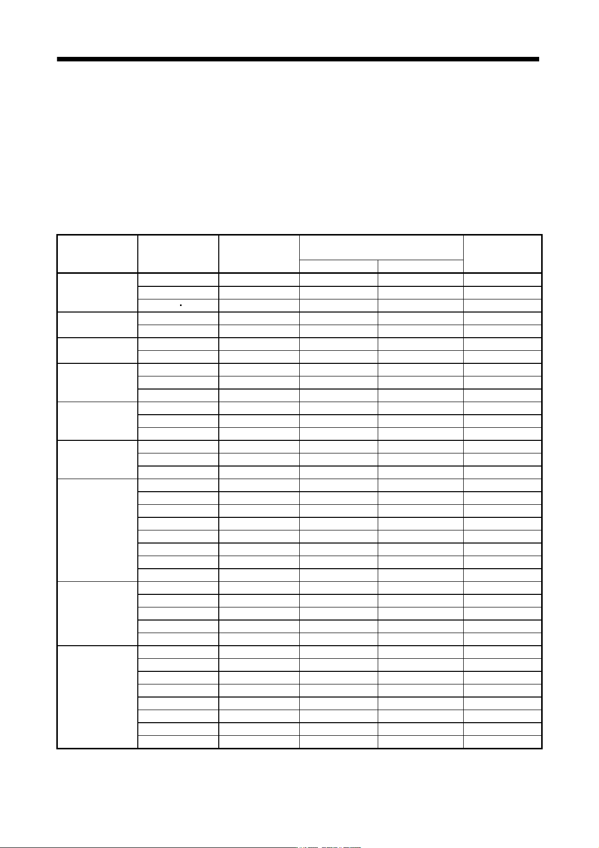
Table 10.1 indicates servo amplifiers' power supply capacities and losses generated under rated load. For
thermal design of an enclosure, use the values in Table 10.1 in consideration for the worst operating
conditions. The actual amount of generated heat will be intermediate between values at rated torque and
servo off according to the duty used during operation. When the servo motor is run at less than the
maximum speed, the power supply capacity will be smaller than the value in the table, but the servo
amplifier's generated heat will not change.
Table 10.1 Power supply capacity and generated heat per servo amplifier at rated output
Servo amplifier Servo motor
(Note 1)
Power supply
capacity[kVA]
(Note 2)
Servo amplifier-generated heat[W]
Area required for
heat dissipation
At rated torque With servo off [m
2
]
MR-J3-10B (1)
HF-MP053 0.3 25 15 0.5
HF-MP13 0.3 25 15 0.5
HF-KP053 13 0.3 25 15 0.5
MR-J3-20B (1)
HF-MP23 0.5 25 15 0.5
HF-KP23 0.5 25 15 0.5
MR-J3-40B (1)
HF-MP43 0.9 35 15 0.7
HF-KP43 0.9 35 15 0.7
MR-J3-60B (4)
HF-SP52 (4) 1.0 40 15 0.8
HF-SP51 1.0 40 15 0.8
HC-LP52 1.0 40 15 0.8
MR-J3-70B
HF-MP73 1.3 50 15 1.0
HF-KP73 1.3 50 15 1.0
HC-UP72 1.3 50 15 1.0
MR-J3-100B (4)
HF-SP102 (4) 1.7 50 15 1.0
HF-SP81 1.5 50 15 1.0
HC-LP102 1.7 50 15 1.0
MR-J3-200B (4)
HF-SP152 (4) 2.5 90 20 1.8
HF-SP202 (4) 3.5 90 20 1.8
HF-SP121 2.1 90 20 1.8
HF-SP201 3.5 90 20 1.8
HC-RP103 1.8 50 15 1.0
HC-RP153 2.5 90 20 1.8
HC-UP152 2.5 90 20 1.8
HC-LP152 2.5 90 20 1.8
MR-J3-350B (4)
HF-SP352 (4) 5.5 130 20 (25) (Note 3) 2.7
HC-RP203 3.5 90 20 1.8
HC-UP202 3.5 90 20 1.8
HC-LP202 3.5 90 20 1.8
HF-SP301 4.8 120 20 2.4
MR-J3-500B (4)
HF-SP502 (4) 7.5 195 25 3.9
HC-RP353 5.5 135 25 2.7
HC-RP503 7.5 195 25 3.9
HC-UP352 5.5 195 25 3.9
HC-UP502 7.5 195 25 3.9
HC-LP302 4.5 120 25 2.4
HA-LP502 7.5 195 25 3.9
HF-SP421 6.7 160 25 3.2