sh030051g.pdf - 第333页
13 - 32 13. SERVO AMPLIFIERS WI TH A LARGE CAPACITY ( 30k TO 55kW ) 13.3.4 How to use the connection ba rs Make sure to use the supplied connection conductors a nd connect the L and L of the drive unit to those of the co…
13 - 31
13. SERVO AMPLIFIERS WITH A LARGE CAPACITY
(
30k TO 55kW
)
13.3.3 Terminal
Refer to section 13.7 for the terminal block arrangement and signal layout.
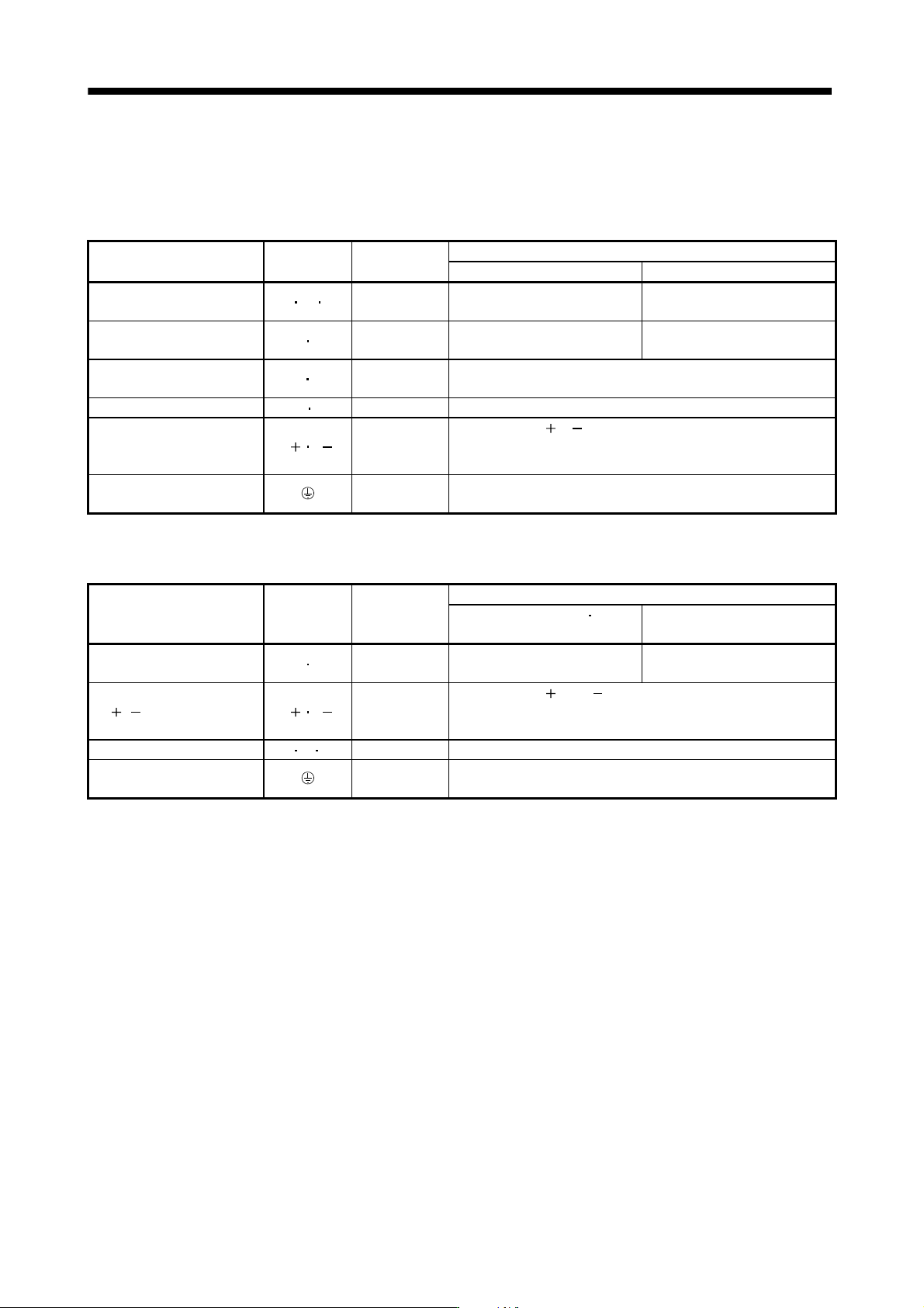
(1) Converter unit
Connection target
(Application)
Abbreviation
(Note)
Terminal block
Description
MR-J3-CR55K MR-J3-CR55K4
Main circuit power supply L1 L2 L3 TE1-1
Connect 3-phase 200 to
230VAC, 50/60Hz to L
1, L2, L3.
Connect 3-phase 380 to
480VAC, 50/60Hz to L1, L2, L3.
Control circuit power supply L11 L21 TE3
Connect 1-phase 200 to
230VAC, 50/60Hz.
Connect 1-phase 380 to
480VAC, 50/60Hz.
Power factor improving
DC reactor
P
1 P2 TE1-2
When using the power factor improving DC reactor, connect it after
removing the connection plate across P
1-P2.
Regenerative brake P2 C TE1-2 Connect to the P
2
and C terminals of the regenerative option.
DC link L L TE2-2
Connect to the L
, L terminals of the drive unit.
Use the connection bar, which is supplied with the drive unit, to
connect.
Grounding PE
Connect this terminal to the protective earth (PE) terminals of the
servo motor and control box for grounding.
Note. The permissible tension applied to any of the terminal blocks TE1-1, TE1-2, TE2-2 is 350[N].
(2) Drive unit
Connection target
(Application)
Abbreviation
(Note)
Terminal block
Description
MR-J3-DU30KB
MR-J3-DU37KB
MR-J3-DU30KB4 to
MR-J3-DU55KB4
Control circuit power supply L11 L21 TE3
Connect 1-phase 200 to
230VAC, 50/60Hz.
Connect 1-phase 380 to
480VAC, 50/60Hz.
L L power supply input L L TE2-1
Connect to the L
and L terminals of the converter unit.
Use the connection bar, which is supplied with the drive unit, to
connect.
Servo motor power U V W TE1A Connect to the servo motor power terminals (U, V, W).
Grounding PE
Connect this terminal to the protective earth (PE) terminals of the
servo motor and control box for grounding.
Note. The permissible tension applied to any of the terminal blocks TE1, TE2-1 is 350[N].
13 - 32
13. SERVO AMPLIFIERS WITH A LARGE CAPACITY
(
30k TO 55kW
)
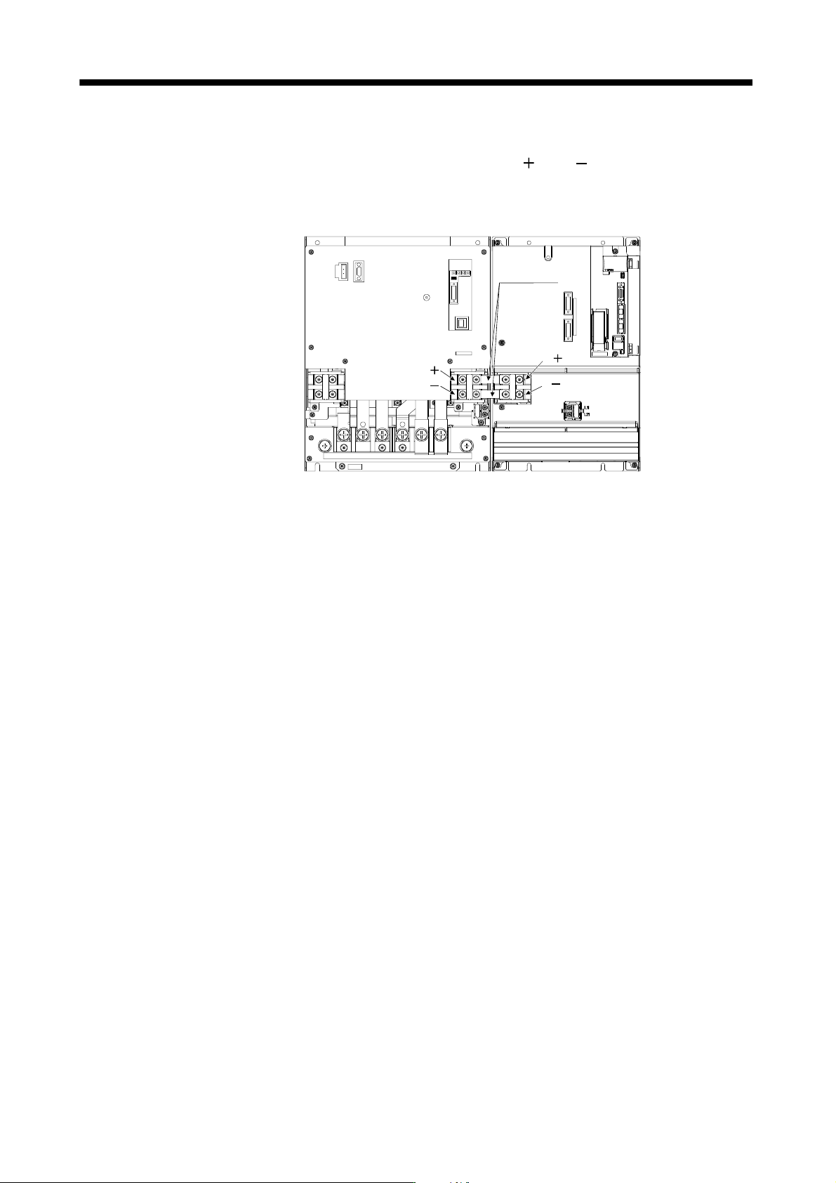
13.3.4 How to use the connection bars
Make sure to use the supplied connection conductors and connect the L
and L of the drive unit to those of
the converter unit as shown below. Never use connection conductors other than the ones supplied with the
drive unit. Both units are shown without the front covers.
L
L
L
L
Connection
conductors
Drive unitConverter unit
13 - 33
13. SERVO AMPLIFIERS WITH A LARGE CAPACITY
(
30k TO 55kW
)
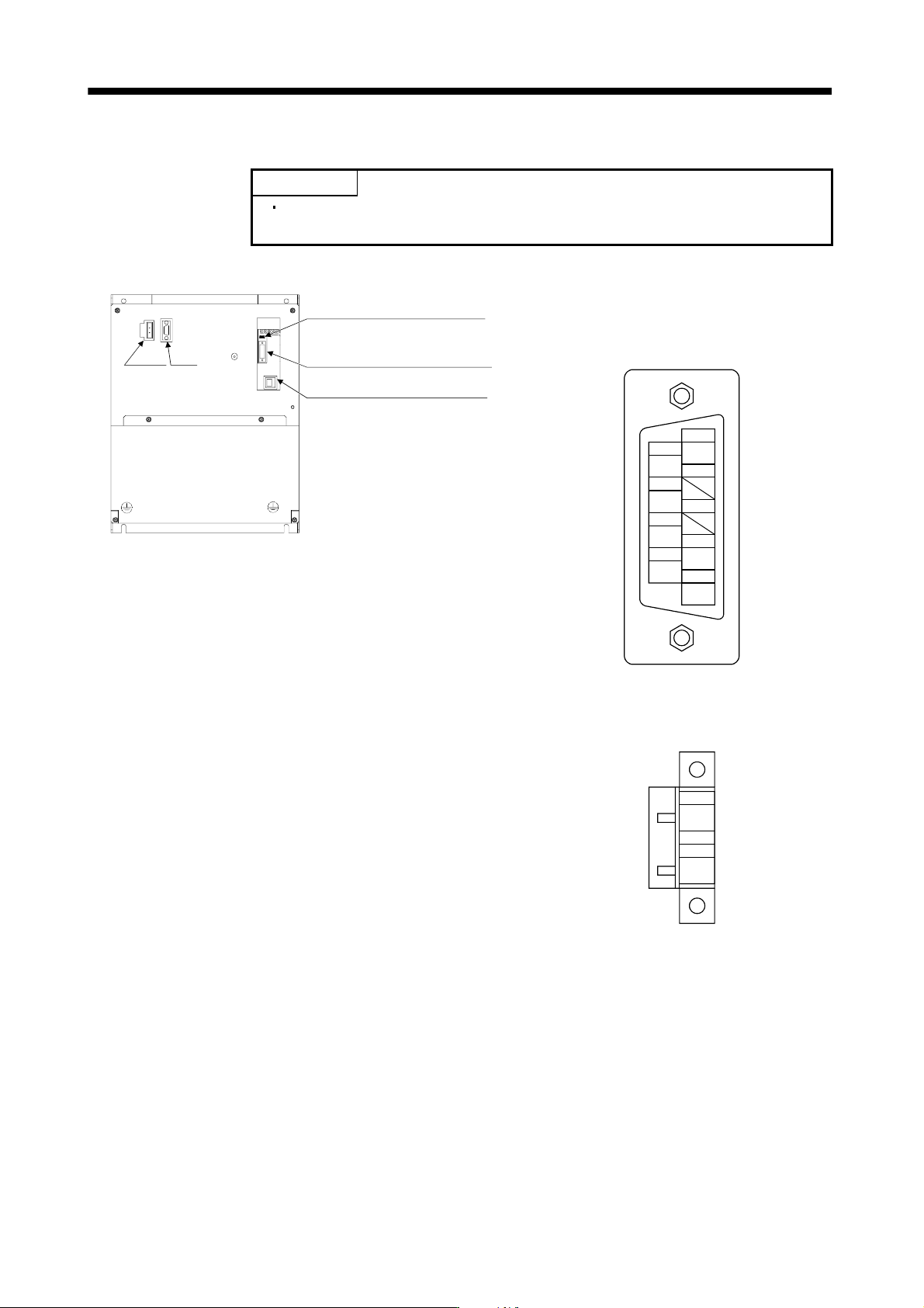
13.3.5 Connectors and signal arrangements
POINT
The pin configurations of the connectors are as viewed from the cable
connector wiring section.
(1) Converter unit
CN6 Leave this open.
CN40 Connect to CN40A of the
drive unit.
CN3 Leave this open.
CHARGE
CNP1 CN1
CN1 (Digital I/O connector)
Model: 17JE-23090-02 (D8A) K11-CG (D-sub 9 pin or
equivalent)
(DDK)
DICOM
WNG
9
DOCOM
5
2
4
6
7
3
1
8
DOCOM
EM1
DICOM
ALM
CNP1 (Magnetic contactor wiring connector)
Model: GFKC 2.5/2-STF-7.62
(Phoenix Contact)
1
MC1
2
MC2