sh030051g.pdf - 第383页
13 - 82 13. SERVO AMPLIFIERS WI TH A LARGE CAPACITY ( 30k TO 55kW ) 13.9.4 Selection example of wires POINT Wires indicated in this section are separated wi res. When using a cable for power line (U, V, and W) between th…
13 - 81
13. SERVO AMPLIFIERS WITH A LARGE CAPACITY
(
30k TO 55kW
)
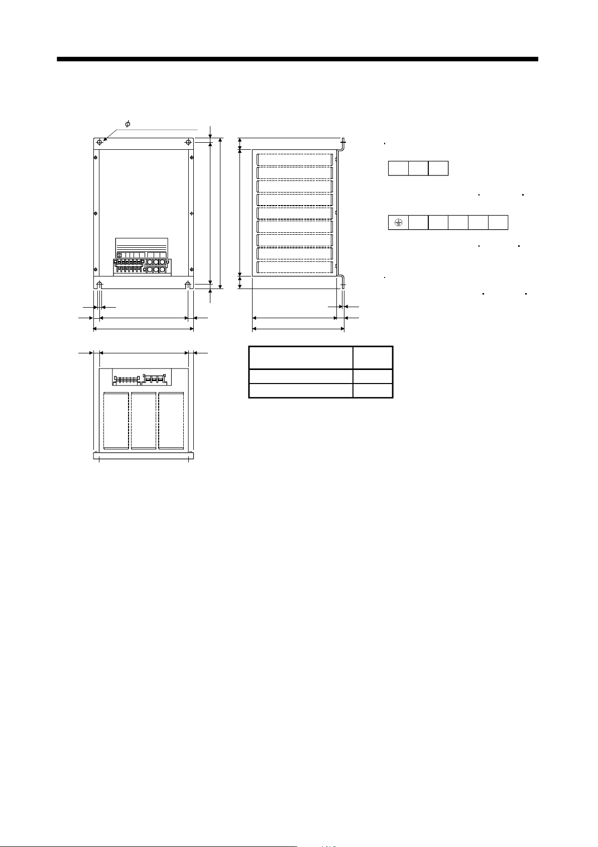
(3) Outline dimension drawing
[Unit:mm]
Terminal block
TE1
Terminal screw: M5
Tightening torque: 2.0 [N m] (17.7 [lb in])
Mounting screw
Screw size: M8
Tightening torque: 13.2 [N m] (117 [lb in])
Terminal screw: M5
Tightening torque: 0.8 [N m] (7.1 [lb in])
TE2
230
15
10
370
10
390
330
3030
10
TE2 TE1
15
230
15 15
260
235
220
15
2.3
UVW
a
b1314
UVW
ab13 14
2- 10 installation hole
DBU-37K
Mass
[kg(lb)]
11(24.25)
8(17.64)
Dynamic brake
DBU-55K-4
13 - 82
13. SERVO AMPLIFIERS WITH A LARGE CAPACITY
(
30k TO 55kW
)
13.9.4 Selection example of wires
POINT
Wires indicated in this section are separated wires. When using a cable for
power line (U, V, and W) between the servo amplifier and servo motor, use a
600V grade EP rubber insulated chloroprene sheath cab-tire cable (2PNCT).
For selection of cables, refer to appendix 6.
To comply with the UL/C-UL (CSA) Standard, use UL-recognized copper
wires rated at 60
(140 ) or more for wiring. To comply with other
standards, use a wire that is complied with each standard
Selection condition of wire size is as follows.
Construction condition: One wire is constructed in the air
Wire length: 30m or less
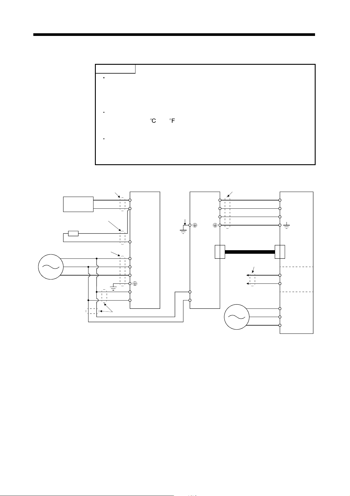
The following diagram shows the wires used for wiring. Use the wires given in this paragraph or equivalent.
Converter unit Drive unit Servo motor
C
P
1
P
2
L
1
L
2
L
3
L
11
L
21
V
U
W
V
U
W
Motor
Encoder
OHS1
OHS2
Cooling fan
BU
BV
BW
L
11
L
21
2) Control power supply lead
3) Motor power supply lead
6) Thermal relay
Encoder cable
5) Cooling fan
lead
3)
Power supply
1)
Power factor
improving
DC reactor
4) Regenerative option lead
Regenerative option
1) Main circuit power
supply lead
Power supply
Thermal
relay
13 - 83
13. SERVO AMPLIFIERS WITH A LARGE CAPACITY
(
30k TO 55kW
)
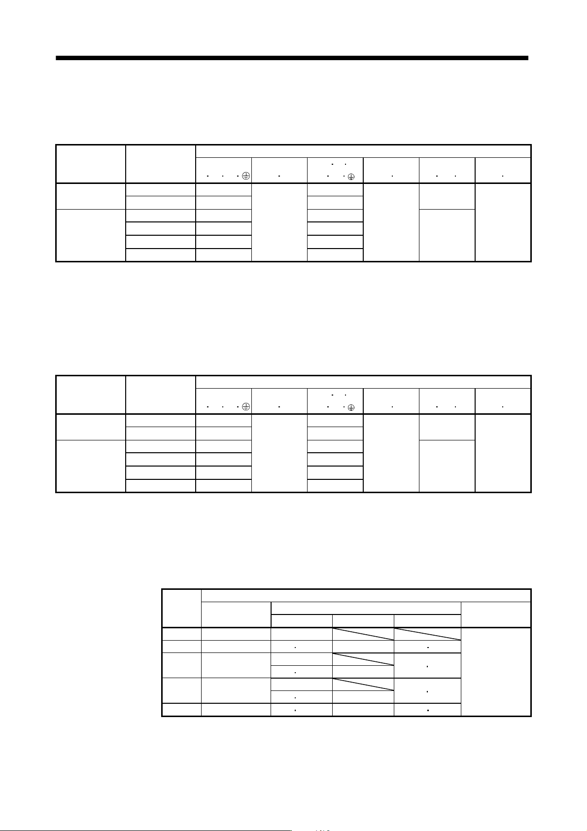
(1) When using the 600V Polyvinyl chloride insulated wire (IV wire)
Selection example of wire size when using IV wires is indicated below.
Table 13.4 Wire size selection example 1 (IV wire)
Converter unit
(Note 2)
Drive unit
Wires[mm
2
] (Note 1, 3)
1)
L
1
L
2
L
3
2)
L
11
L
21
3) U
V W
P
1
P
2
4)
P
2
C
5)
BU BV BW
6)
OHS1 OHS2
MR-J3-CR55K
MR-J3-DU30KB 50(AWG1/0): d 60(AWG2/0): d
2(AWG14)
MR-J3-DU37KB 60(AWG2/0): d (Note 4)
MR-J3-DU30KB4 22(AWG4): b
2(AWG14)
30(AWG2): c
5.5(AWG10): a
1.25(AWG16)
MR-J3-CR55K4
MR-J3-DU37KB4 30(AWG2): c 38(AWG2): c
1.25(AWG16)
MR-J3-DU45KB4 38(AWG2): c 50(AWG1/0): d
MR-J3-DU55KB4 50(AWG1/0): d 60(AWG2/0): d
Note 1. Alphabets in the table indicate crimping tools. For crimping terminals and applicable tools, refer to (3) in this section.
2. When connecting to the terminal block, be sure to use the screws which are provided with the terminal block.
3. For the servo motor with a cooling fan.
4. Wires are selected based on the highest rated current among combining servo motors.
(2) When using the 600V Grade heat-resistant polyvinyl chloride insulated wire (HIV wire)
Selection example of wire size when using HIV wires is indicated below.
Table 13.5 Wire size selection example 2 (HIV wire)
Converter unit
(Note 2)
Drive unit
Wires[mm
2
] (Note 1, 3)
1)
L
1
L
2
L
3
2)
L
11
L
21
3) U
V W
P
1
P
2
4)
P
2
C
5)
BU BV BW
6)
OHS1 OHS2
MR-J3-CR55K
MR-J3-DU30KB 38(AWG2): c 60(AWG2/0): d
2(AWG14)
MR-J3-DU37KB 60(AWG2/0): d 60(AWG2/0): d
MR-J3-DU30KB4 22(AWG4): b
2(AWG14)
22(AWG4): e
5.5(AWG10): a
1.25(AWG16)
MR-J3-CR55K4
MR-J3-DU37KB4 22(AWG4): b 22(AWG4): e
1.25(AWG16)
MR-J3-DU45KB4 38(AWG2): c 38(AWG2): c
MR-J3-DU55KB4 38(AWG2): c 38(AWG2): c
Note 1. Alphabets in the table indicate crimping tools. For crimping terminals and applicable tools, refer to (3) in this section.
2. When connecting to the terminal block, be sure to use the screws which are provided with the terminal block.
3. For the servo motor with a cooling fan.
(3) Selection example of crimping terminals
The table below shows a selection example of crimping terminals for the servo amplifier terminal block
when using the wires mentioned in (1) and (2) in this section.
Symbol
Servo amplifier side crimping terminals
(Note 2)
Crimping terminal
Applicable tool
Manufacturer
Body Head Dice
a FVD5.5-10 YNT-1210S
Japan Solderless
Terminal
b FVD22-10 YF-1 E-4 YNE-38 DH-123 DH113
(Note 1)
c
R38-8
R38-10
YPT-60-21
TD-124
TD112
YF-1 E-4 YET-60-1
(Note 1)
d
R60-10
YPT-60-21
TD-125
TD113
YF-1 E-4 YET-60-1
e FVD22-8 YF-1 E-4 YNE-38 DH-123 DH-113
Note 1. Coat the part of crimping with the insulation tube.
2. Make sure to use recommended crimping terminals or equivalent since some crimping terminals
cannot be installed depending on the size.