sh030051g.pdf - 第275页
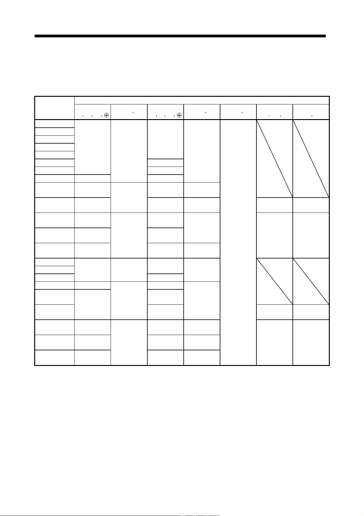
11 - 70 11. OPTIONS AND AUXILI ARY EQUIPMENT (c) Selection example of crimping termin als Selection example of crimping terminals for the se rvo amplifier terminal box when using the wires mentioned in (1) (a) and (b) in…
11 - 69
11. OPTIONS AND AUXILIARY EQUIPMENT
(b) When using the 600V Grade heat-resistant polyvinyl chloride insulated wire (HIV wire)
Selection example of wire size when using HIV wires is indicated below. For the wire (8)) for power
regeneration converter (FR-RC-(H)), use the IV wire indicated in (1) (a) in this section.
Table 11.2 Wire size selection example 2 (HIV wire)
Servo amplifier
Wires [mm
2
] (Note 1, 4)
1)
L
1 L2 L3
2) L11 L21
3)
U
V W
4) P C 5) B1 B2
6)
BU
BV BW
7)
OHS1 OHS2
MR-J3-10B(1)
MR-J3-20B(1)
MR-J3-40B(1) 1.25(AWG16)
MR-J3-60B 2(AWG14)
1.25(AWG16)
2(AWG14)
MR-J3-70B
MR-J3-100B 1.25(AWG16)
MR-J3-200B 2(AWG14)
MR-J3-350B 3.5(AWG12) 3.5(AWG12)
MR-J3-500B
(Note 2)
5.5(AWG10): a
1.25(AWG16):
h
5.5(AWG10): a 2(AWG14): g
MR-J3-700B
(Note 2)
8(AWG8): b 8(AWG8): b 2(AWG14): g
1.25(AWG16)
(Note 3)
1.25(AWG16)
(Note 3)
MR-J3-11KB
(Note 2)
14(AWG6): c 14(AWG6): c
3.5(AWG12): j 1.25(AWG16)
MR-J3-15KB
(Note 2)
22(AWG4): d
1.25(AWG16):
g
22(AWG4): d 1.25(AWG16) 1.25(AWG16)
MR-J3-22KB
(Note 2)
38(AWG1): p 38(AWG1): p 5.5(AWG10): k
MR-J3-60B4
1.25(AWG16)
MR-J3-100B4 2(AWG14) 1.25(AWG16) 2(AWG14)
MR-J3-200B4 2(AWG14)
MR-J3-350B4 2(AWG14): g
1.25(AWG16):
h
2(AWG14): g
2(AWG14): g
MR-J3-500B4
(Note 2)
3.5(AWG12): a
3.5(AWG12): a
MR-J3-700B4
(Note 2)
5.5(AWG10): a
1.25(AWG16)
(Note 3)
1.25(AWG16)
(Note 3)
MR-J3-11KB4
(Note 2)
5.5(AWG10): j 8(AWG8): l 2(AWG14): q
MR-J3-15KB4
(Note 2)
8(AWG8): l
1.25(AWG16):
g
14(AWG6): c 3.5(AWG12): j 1.25(AWG16) 1.25(AWG16)
MR-J3-22KB4
(Note 2)
14(AWG6): m 14(AWG6): m 3.5(AWG12): k
Note 1. Alphabets in the table indicate crimping tools. For crimping terminals and applicable tools, refer to (1) (c) in this section.
2. When connecting to the terminal block, be sure to use the screws which are provided with the terminal block.
3. For the servo motor with a cooling fan.
4. Wires are selected based on the highest rated current among combining servo motors.
11 - 70
11. OPTIONS AND AUXILIARY EQUIPMENT
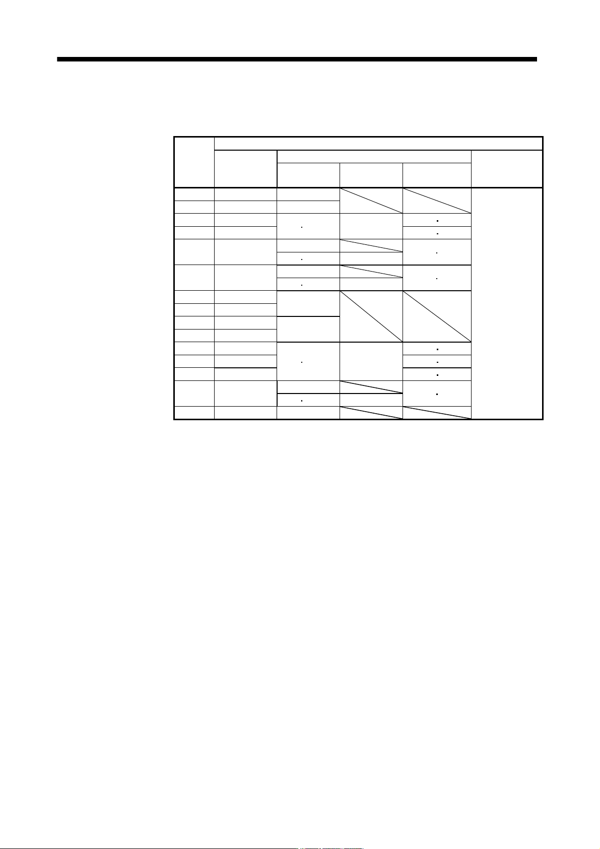
(c) Selection example of crimping terminals
Selection example of crimping terminals for the servo amplifier terminal box when using the wires
mentioned in (1) (a) and (b) in this section is indicated below.
Symbol
Servo amplifier side crimping terminals
(Note 2)
Crimping
terminal
Applicable tool
Manufacturer
Body Head Dice
a FVD5.5-4 YNT-1210S
Japan Solderless
Terminal
(Note 1)b 8-4NS YHT-8S
c FVD14-6
YF-1
E-4 YNE-38
DH-112
DH122
d FVD22-6 DH-113 DH123
(Note 1)e 38-6
YPT-60-21
TD-112 TD-124
YF-1 E-4 YET-60-1
(Note 1)f R60-8
YPT-60-21
TD-113 TD-125
YF-1 E-4 YET-60-1
g FVD2-4
YNT-1614
h FVD2-M3
j FVD5.5-6
YNT-1210S
k FVD5.5-8
l FVD8-6
YF-1
E-4 YNE-38
DH-111
DH121
m FVD14-8 DH-112 DH122
n FVD22-8 DH-113 DH123
(Note 1)p R38-8
YPT-60-21
TD-112 TD-124
YF-1 E-4 YET-60-1
q FVD2-6 YNT-1614
Note 1. Coat the part of crimping with the insulation tube.
2. Some crimping terminals may not be mounted depending on the size. Make sure to use the
recommended ones or equivalent ones.
11 - 71
11. OPTIONS AND AUXILIARY EQUIPMENT
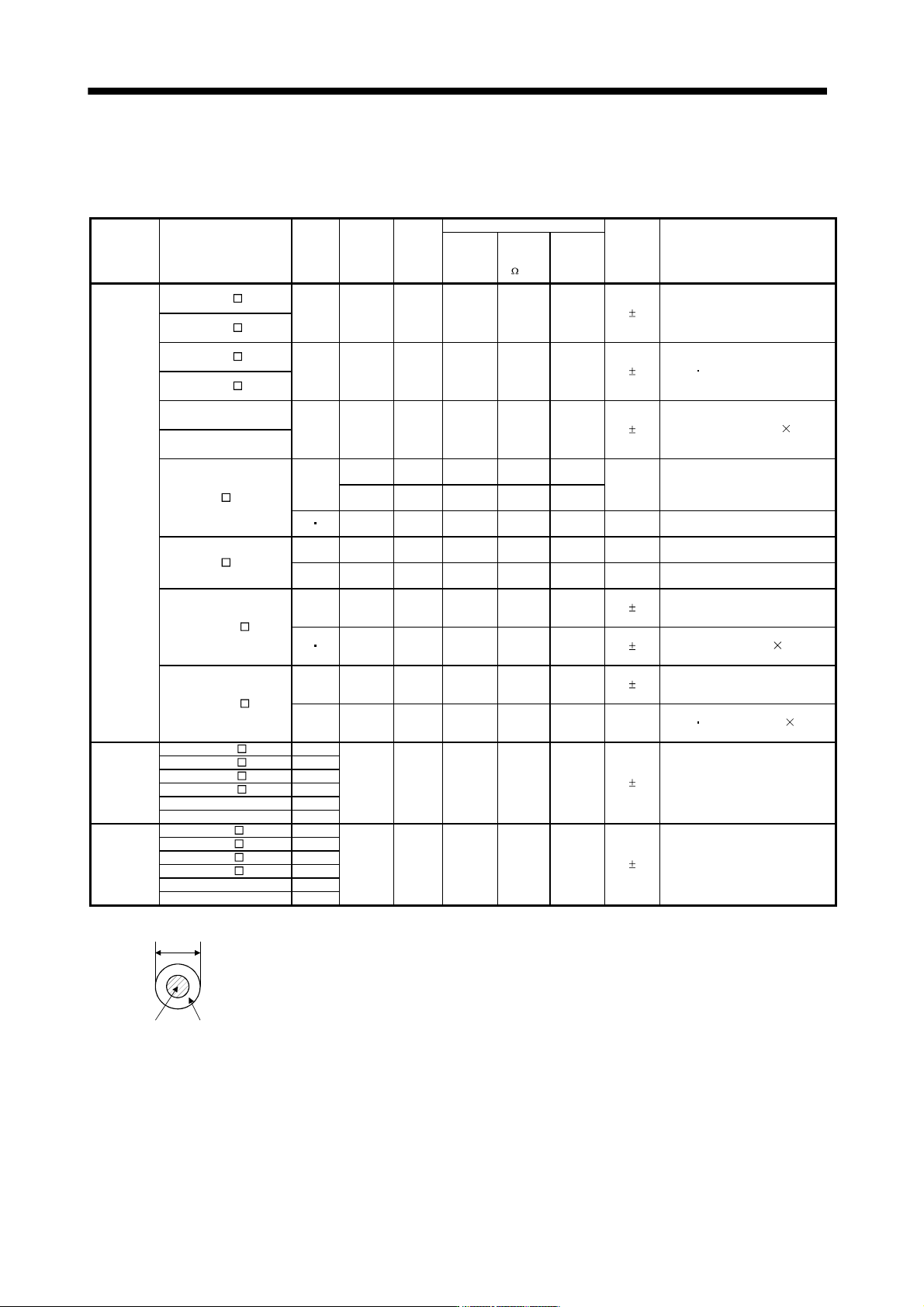
(2) Wires for cables
When fabricating a cable, use the wire models given in the following table or equivalent.
Table 11.3 Wires for option cables
Type Model
Length
[m]
Core size
[mm
2
]
Number
of Cores
Characteristics of one core
(Note 3)
Finishing
OD [mm]
Wire model
Structure
[Wires/mm]
Conductor
resistance
[ /mm]
Insulation
coating OD
d [mm]
(Note 1)
Encoder
cable
MR-J3ENCBL
M-A1-L
2 to 10 AWG22
6
(3 pairs)
7/0.26
53
or less
1.2 7.1
0.3
(Note 3)
VSVP 7/0.26 (AWG#22 or
equivalent)-3P
Ban-gi-shi-16823
MR-J3ENCBL M-A2-L
MR-J3ENCBL M-A1-H
2 to 10 AWG22
6
(3 pairs)
70/0.08
56
or less
1.2 7.1
0.3
(Note 3)
ETFE SVP 70/0.08 (AWG#22 or
equivalent)-3P Ban-gi-shi-16824
MR-J3ENCBL M-A2-H
MR-J3JCBL03M-A1-L
0.3 AWG26
8
(4 pairs)
30/0.08
233
or less
1.2 7.1
0.3
(Note 5)
T/2464-1061/II A-SB 4P
26AWG
MR-J3JCBL03M-A2-L
MR-EKCBL M-L
2 to 10
0.3mm
2
4
(2 pairs)
12/0.18
65.7
or less
1.3
7.3
(Note 3)
20276 composite 4-pair shielded
cable (A-TYPE)
0.08mm
2
4
(2 pairs)
7/0.127
234
or less
0.67
20 30 0.3mm
2
12
(6 pairs)
12/0.18
63.6
or less
1.2 8.2 UL20276 AWG#23 6pair(BLACK)
MR-EKCBL M-H
20 0.2mm
2
12
(6 pairs)
40/0.08
105
or less
0.88 7.2 (Note 3) A14B2343 6P
30 to 50 0.2mm
2
14
(7 pairs)
40/0.08
105
or less
0.88 8.0 (Note 3) J14B0238(0.2*7P)
MR-J3ENSCBL M-L
2 to 10 AWG22
6
(3 pairs)
7/0.26
53
or less
1.2 7.1
0.3
(Note 3)
VSVP 7/0.26 (Equivalent to
AWG#22)-3P Ban-gi-shi-16823
20 30 AWG23
12
(6 pairs)
12/0.18
63.3
or less
1.2 8.2
0.3
(Note 3)
20276 VSVCAWG#23 6P
Ban-gi-shi-15038
MR-J3ENSCBL M-H
2 to 10 AWG22
6
(3 pairs)
70/0.08
56
or less
1.2 7.1
0.3
(Note 3)
ETEF SVP 70/0.08 (Equivalent to
AWG#22)-3P Ban-gi-shi-16824
20 to 50 AWG24
12
(6 pairs)
40/0.08
105
or less
0.88 7.2
(Note 3)
ETFE
SVP 40/0.08mm 6P
Ban-gi-shi-15266
Motor power
supply cable
MR-PWS1CBL
M-A1-L 2 to 10
(Note 6)
AWG19
4 50/0.08
25.40
or less
1.8 5.7
0.3
(Note 4)
UL Style 2103 AWG19 4 cores
MR-PWS1CBL M-A2-L 2 to 10
MR-PWS1CBL M-A1-H 2 to 10
MR-PWS1CBL M-A2-H 2 to 10
MR-PWS2CBL03M-A1-L 0.3
MR-PWS2CBL03M-A2-L 0.3
Motor brake
cable
MR-BKS1CBL
M-A1-L 2 to 10
(Note 6)
AWG20
2 100/0.08
38.14
or less
1.3 4.0
0.3
(Note 4)
UL Style 2103 AWG20 2 cores
MR-BKS1CBL M-A2-L 2 to 10
MR-BKS1CBL M-A1-H 2 to 10
MR-BKS1CBL M-A2-H 2 to 10
MR-BKS2CBL03M-A1-L 0.3
MR-BKS2CBL03M-A2-L 0.3
Note 1. d is as shown below.
d
Conductor
Insulation sheath
2. Purchased from Toa Electric Industry
3. Standard OD. Max. OD is about 10% greater.
4. Kurabe
5. Taiyo Electric Wire and Cable
6. These wire sizes assume that the UL-compliant wires are used at the wiring length of 10m.