sh030051g.pdf - 第11页
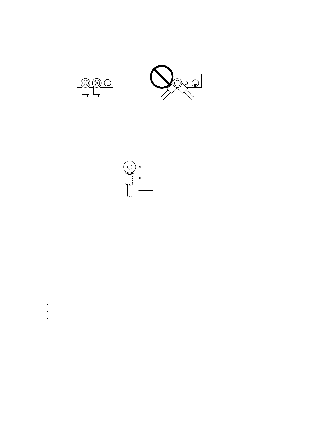
A - 10 (b) Do not connect two ground cables to the same protective e arth (PE) terminal. Always connect the cables to the terminals one- to-one. PE termi nals PE terminals (c) If a leakage current breaker is used to prev…
A - 9
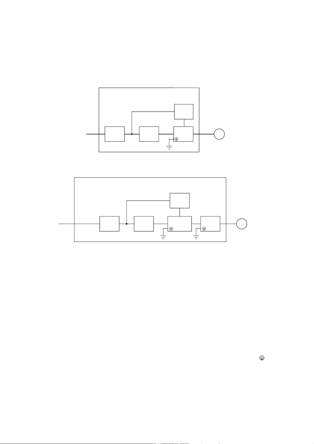
(2) Configuration
The control circuit provide safe separation to the main circuit in the converter unit and servo amplifier (drive
unit).
(a) MR-J3-22KB(4) or less
NFB MC
24VDC
power
supply
Servo
amplifier
Reinforced
insulating type
Control box
Servo
motor
No-fuse
breaker
Magnetic
contactor
M
(b) MR-J3-DU30KB(4) or more
NFB MC
24VDC
power
supply
Control box
No-fuse
breaker
Magnetic
contactor
Converter
unit
Servo
motor
M
Drive
unit
Reinforced
insulating type
(3) Environment
Operate the converter unit and servo amplifier (drive unit) at or above the contamination level 2 set forth in
IEC60664-1. For this purpose, install the converter unit and servo amplifier (drive unit) in a control box
which is protected against water, oil, carbon, dust, dirt, etc. (IP54).
(4) Power supply
(a) This converter unit and servo amplifier (drive unit) can be supplied from star-connected supply with
earthed neutral point of overvoltage category III set forth in IEC60664-1. However, when using the
neutral point of 400V class for single-phase supply, a reinforced insulating transformer is required in the
power input section.
(b) When supplying interface power from external, use a 24VDC power supply which has been insulation-
reinforced in I/O.
(5) Grounding
(a) To prevent an electric shock, always connect the protective earth (PE) terminals (marked
) of the
converter unit and servo amplifier (drive unit) to the protective earth (PE) of the control box.
A - 10
(b) Do not connect two ground cables to the same protective earth (PE) terminal. Always connect the
cables to the terminals one-to-one.
PE terminals
PE terminals
(c) If a leakage current breaker is used to prevent an electric shock, the protective earth (PE) terminals of
the converter unit and servo amplifier (drive unit) must be connected to the corresponding earth
terminals.
(6) Wiring
(a) The cables to be connected to the terminal block of the converter unit and servo amplifier (drive unit)
must have crimping terminals provided with insulating tubes to prevent contact with adjacent terminals.
Crimping terminal
Insulating tube
Cable
(b) Use the servo motor side power connector which complies with the EN Standard. The EN Standard
compliant power connector sets are available from us as options. (Refer to section 11.1)
(7) Auxiliary equipment and options
(a) The no-fuse breaker and magnetic contactor used should be the EN or IEC standard-compliant
products of the models described in section 11.12 (Section 13.9.5 for 30kW or more).
Use a type B (Note) breaker. When it is not used, provide insulation between the converter unit, servo
amplifier (drive unit) and other device by double insulation or reinforced insulation, or install a
transformer between the main power supply, converter unit and servo amplifier (drive unit).
Note. Type A: AC and pulse detectable
Type B: Both AC and DC detectable
(b) The sizes of the cables described in section 11.8 meet the following requirements. To meet the other
requirements, follow Table 5 and Appendix C in EN60204-1.
Ambient temperature: 40 (104) [°C (°F)]
Sheath: PVC (polyvinyl chloride)
Installed on wall surface or open table tray
(c) Use the EMC filter for noise reduction.
(8) Performing EMC tests
When EMC tests are run on a machine/device into which the converter unit and servo amplifier (drive unit)
has been installed, it must conform to the electromagnetic compatibility (immunity/emission) standards after
it has satisfied the operating environment/electrical equipment specifications.
For the other EMC directive guidelines on the converter unit and servo amplifier (drive unit), refer to the
EMC Installation Guidelines(IB(NA)67310).

A - 11
CONFORMANCE WITH UL/C-UL STANDARD
(1) Converter unit, servo amplifiers (drive unit) and servo motors used
Use the converter unit, servo amplifiers (drive unit) and servo motors which comply with the standard model.
Converter unit series :MR-J3-CR55K
MR-J3-CR55K4
Servo amplifier (drive unit) series :MR-J3-10B to MR-J3-22KB
MR-J3-10B1 to MR-J3-40B1
MR-J3-60B4 to MR-J3-22KB4
MR-J3-DU30KB to MR-J3-DU37KB
MR-J3-DU30KB4 to MR-J3-DU55KB4
Servo motor series :HF-MP
HF-KP
HF-SP
(Note)
HF-SP
4 (Note)
HC-RP
HC-UP
HC-LP
HA-LP
(Note)
HA-LP
4 (Note)
Note. For the latest information of compliance, contact Mitsubishi.
(2) Installation
Install a fan of 100CFM (2.8m
3
/min) air flow 4[in] (10.16[cm]) above the servo amplifier (drive unit) or
provide cooling of at least equivalent capability to ensure that the ambient temperature conforms to the
environment conditions (55
or less).
(3) Short circuit rating: SCCR (Short Circuit Current Rating)
This servo amplifier (drive unit) conforms to the circuit whose peak current is limited to 100kA or less,
500Volts Maximum. Having been subjected to the short-circuit tests of the UL in the alternating-current
circuit, the servo amplifier (drive unit) conforms to the above circuit.