sh030051g.pdf - 第25页
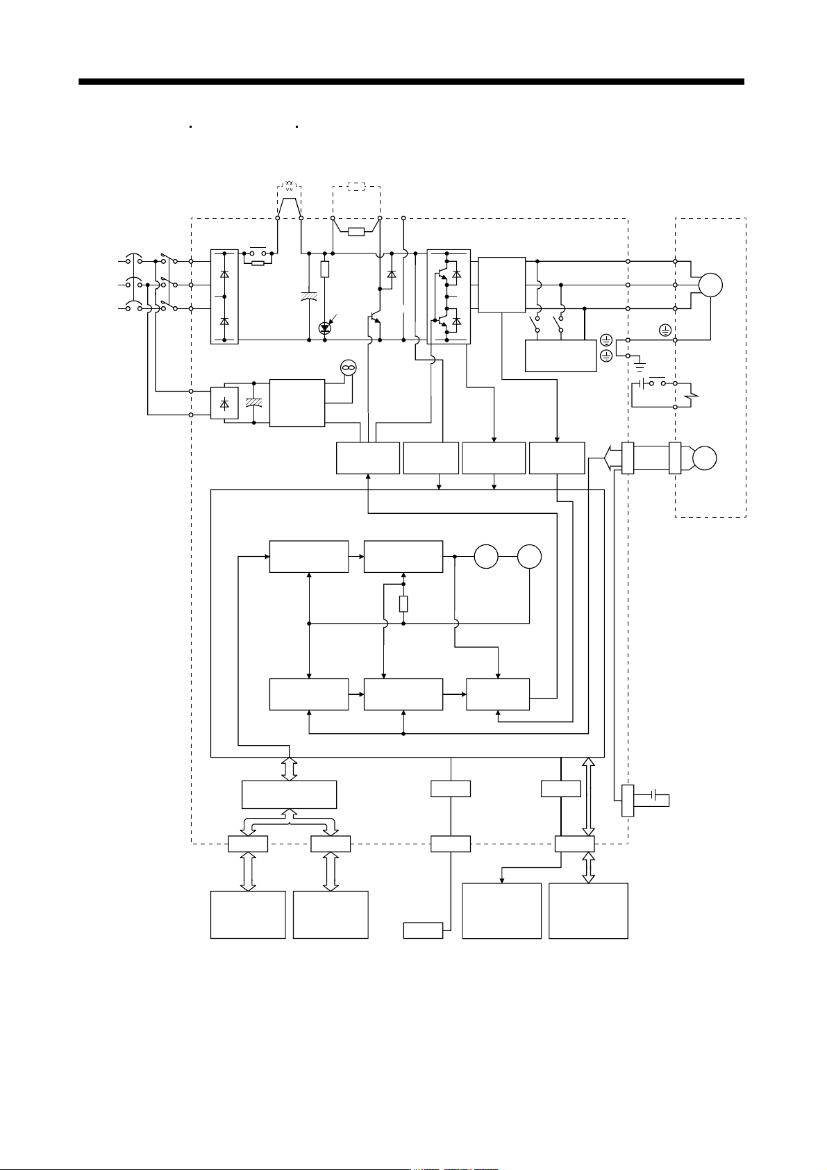
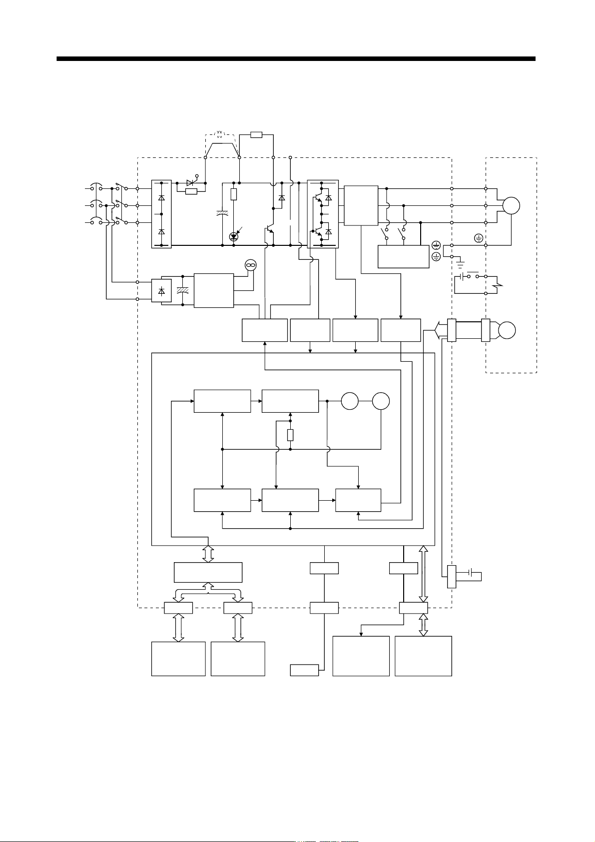
1 - 4 1. FUNCTIONS AND CONFIGURATIO N (3) MR-J3-11KB(4) to 22KB(4) Cooling f an Base amplifier CN4 N C Encoder Current detec tion CN5 NFB MC L 1 L 2 L 3 L 11 L 21 B2 U V W B1 USB USB Power factor improvi ng DC reactor Re…
1 - 3
1. FUNCTIONS AND CONFIGURATION
(2) MR-J3-350B4
MR-J3-500B(4) MR-J3-700B(4)
Base
amplifier
CN4
N
C
Encoder
Current
detection
CN5
NFB MC
L
1
L
2
L
3
L
11
L
21
B2
U
V
W
B1
USB
USB
Power factor
improving DC
reactor
Regenerative
option
MR-J3BAT
P
1
P
2
D/A
Position
command
input
(Note)
Power
supply
CHARGE
lamp
Regene-
rative
TR
Current
detector
Dynamic
brake
Electro-
magnetic
brake
Servo motorServo amplifier
Optional battery
(for absolute position
detection system)
Overcurrent
protection
Voltage
detection
Virtual
encoder
Virtual
motor
Model
torque
Personal
computer
Actual speed
control
Actual position
control
Cooling fan
Control
circuit
power
supply
Model position
control
Model
position
Model
speed
CN2
P
U
V
W
M
Model speed
control
Current
control
I/F Control
CN1BCN1A
Controller or
servo amplifier
Servo amplifier
or cap
Analog monitor
(2 channels)
CN3
Digital I/O
control
Diode
stack
Relay
RA
24VDC
Note. Refer to section 1.3 for the power supply specification.
1 - 4
1. FUNCTIONS AND CONFIGURATION
(3) MR-J3-11KB(4) to 22KB(4)
Cooling fan
Base
amplifier
CN4
N
C
Encoder
Current
detection
CN5
NFB MC
L
1
L
2
L
3
L
11
L
21
B2
U
V
W
B1
USB
USB
Power factor
improving DC
reactor
Regenerative
option
MR-J3BAT
P
1
D/A
Position
command
input
(Note)
Power
supply
CHARGE
lamp
Regene-
rative
TR
Current
detector
Dynamic
brake
Electro-
magnetic
brake
Servo motorServo amplifier
Optional battery
(for absolute position
detection system)
Overcurrent
protection
Voltage
detection
Virtual
encoder
Virtual
motor
Model
torque
Personal
computer
Actual speed
control
Actual position
control
Control
circuit
power
supply
Model position
control
Model
position
Model
speed
CN2
P
U
V
W
M
Model speed
control
Current
control
I/F Control
CN1BCN1A
Controller or
servo amplifier
Servo amplifier
or cap
Analog monitor
(2 channels)
CN3
Digital I/O
control
Diode
stack
Thyristor
RA
24VDC
Note. Refer to section 1.3 for the power supply specification.
1 - 5
1. FUNCTIONS AND CONFIGURATION
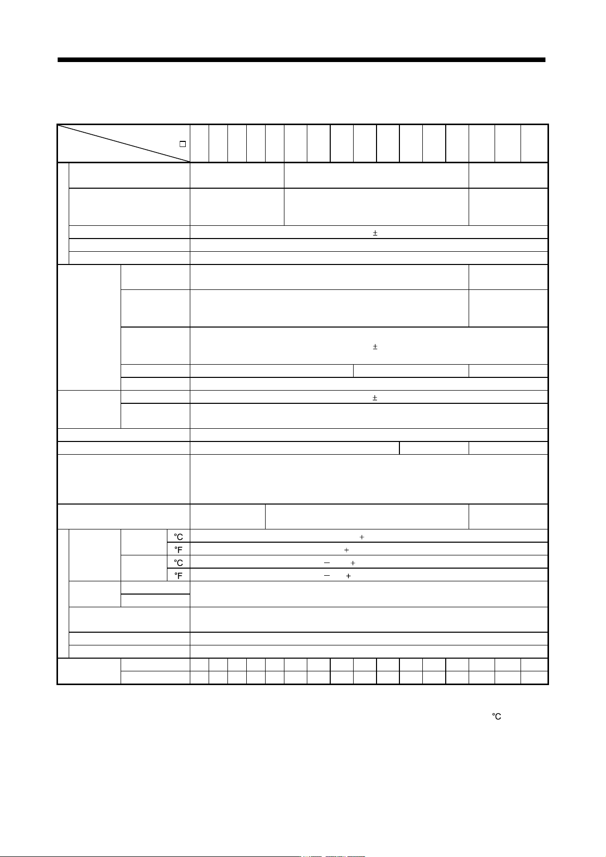
1.3 Servo amplifier standard specifications
(1) 200V class, 100V class
Servo amplifier
MR-J3-
Item
10B 20B 40B 60B 70B 100B 200B 350B 500B 700B 11KB 15KB 22KB 10B1 20B1 40B1
Power su
pp
l
y
Voltage/frequency
3-phase or 1-phase 200
to 230VAC, 50/60Hz
3-phase 200 to 230VAC, 50/60Hz
1-phase 100V to
120VAC, 50/60Hz
Permissible voltage fluctuation
3-phase or 1-phase 200
to 230VAC: 170 to
253VAC
3-phase 170 to 253VAC
1-phase 85 to
132VAC
Permissible frequency fluctuation Within 5%
Power supply capacity Refer to section 10.2
Inrush current Refer to section 10.5
Control circuit
power supply
Voltage,
frequency
1-phase 200 to 230VAC, 50/60Hz
1-phase 100 to
120VAC, 50/60Hz
Permissible
voltage
fluctuation
1-phase 170 to 253VAC
1-phase 85 to
132VAC
Permissible
frequency
fluctuation
Within
5%
Input 30W 45W 30W
Inrush current Refer to section 10.5
Interface power
supply
Voltage 24VDC
10%
Power supply
capacity
(Note 1) 150mA or more
Control System Sine-wave PWM control, current control system
Dynamic brake Built-in External option Built-in
Protective functions
Overcurrent shut-off, regenerative overvoltage shut-off, overload shut-off (electronic thermal relay),
servo motor overheat protection, encoder error protection, regenerative error protection,
undervoltage, instantaneous power failure protection, overspeed protection, excessive error
protection.
Structure
Self-cooled, open
(IP00)
Force-cooling, open (IP00)
Self-cooled, open
(IP00)
Environment
Ambient
temperature
In
operation
[
] (Note 2) 0 to 55 (non-freezing)
[ ] 32 to 131 (non-freezing)
In storage
[
] 20 to 65 (non-freezing)
[ ] 4 to 149 (non-freezing)
Ambient
humidity
In operation
90%RH or less (non-condensing)
In storage
Ambient
Indoors (no direct sunlight)
Free from corrosive gas, flammable gas, oil mist, dust and dirt
Altitude Max. 1000m above sea level
Vibration 5.9 [m/s
2
] or less
Mass
[kg] 0.8 0.8 1.0 1.0 1.4 1.4 2.1 2.3 4.6 6.2 18 18 19 0.8 0.8 1.0
[lb] 1.76 1.76 2.21 2.21 3.09 3.09 4.63 5.07 10.1 13.7 39.7 39.7 41.9 1.76 1.76 2.21
Note 1. 150mA is the value applicable when all I/O signals are used. The current capacity can be decreased by reducing the number of
I/O points.
2. When closely mounting the servo amplifier of 3.5kW or less, operate them at the ambient temperatures of 0 to 45
or at 75% or
smaller effective load ratio.