sh030051g.pdf - 第147页
6 - 2 6. GENERAL GAIN ADJUSTMEN T (2) Adjustment sequence and mode usage END Inter polatio n made for 2 or more axes? START Operation Auto tuning mode 2 OK? OK? Manual mode OK? No No Yes No Yes No Yes Auto tuning mode 1 …
6 - 1
6. GENERAL GAIN ADJUSTMENT
6. GENERAL GAIN ADJUSTMENT
6.1 Different adjustment methods
6.1.1 Adjustment on a single servo amplifier
The gain adjustment in this section can be made on a single servo amplifier. For gain adjustment, first execute
auto tuning mode 1. If you are not satisfied with the results, execute auto tuning mode 2 and manual mode in
this order.
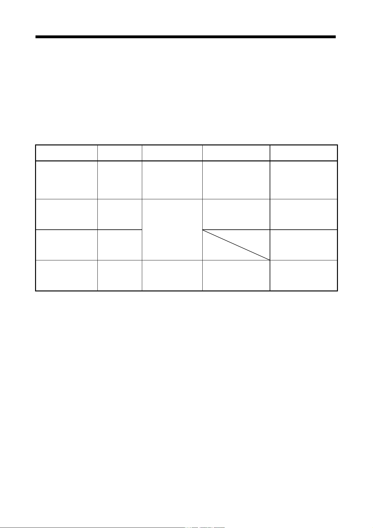
(1) Gain adjustment mode explanation
Gain adjustment mode
Parameter
No.PA08 setting
Estimation of load inertia
moment ratio
Automatically set
parameters
Manually set parameters
Auto tuning mode 1
(initial value)
0001 Always estimated GD2 (parameter No.PB06)
PG2 (parameter No.PB08)
PG1 (parameter No.PB07)
VG2 (parameter No.PB09)
VIC (parameter No.PB10)
Response level setting of
parameter No.2
Auto tuning mode 2 0002 Fixed to parameter No.
PB06 value
PG2 (parameter No.PB08)
PG1 (parameter No.PB07)
VG2 (parameter No.PB09)
VIC (parameter No.PB10)
GD2 (parameter No.PB06)
Response level setting of
parameter No.PA09
Manual mode 0003 PG1 (parameter No.PB07)
GD2 (parameter No.PB06)
VG2 (parameter No.PB09)
VIC (parameter No.PB10)
Interpolation mode 0000 Always estimated GD2 (parameter No.PB06)
PG2 (parameter No.PB08)
VG2 (parameter No.PB09)
VIC (parameter No.PB10)
PG1 (parameter No.PB07)
6 - 2
6. GENERAL GAIN ADJUSTMENT
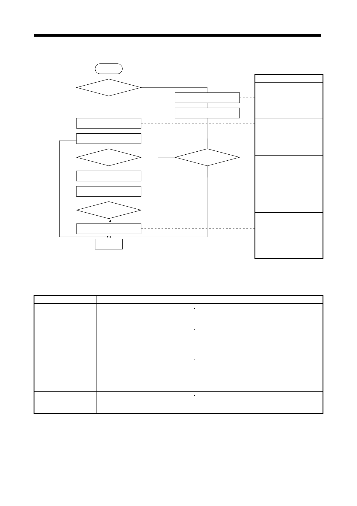
(2) Adjustment sequence and mode usage
END
Interpolation
made for 2 or more
axes?
START
Operation
Auto tuning mode 2
OK?
OK?
Manual mode
OK?
No
No
Yes
No
Yes
No
Yes
Auto tuning mode 1
Operation
Interpolation mode
Operation
Yes
Usage
Used when you want to
match the position gain (PG1)
between 2 or more axes.
Normally not used for other
purposes.
Allows adjustment by merely
changing the response level
setting.
First use this mode to make
adjustment.
Used when the conditions of
auto tuning mode 1 are not
met and the load inertia
moment ratio could not be
estimated properly, for
example.
You can adjust all gains
manually when you want to
do fast settling or the like.
6.1.2 Adjustment using MR Configurator
This section gives the functions and adjustment that may be performed by using the servo amplifier with the
MR Configurator which operates on a personal computer.
Function Description Adjustment
Machine analyzer With the machine and servo motor coupled,
the characteristic of the mechanical system
can be measured by giving a random
vibration command from the personal
computer to the servo and measuring the
machine response.
You can grasp the machine resonance frequency and
determine the notch frequency of the machine resonance
suppression filter.
You can automatically set the optimum gains in response to
the machine characteristic. This simple adjustment is
suitable for a machine which has large machine resonance
and does not require much settling time.
Gain search Executing gain search under to-and-fro
positioning command measures settling
characteristic while simultaneously
changing gains, and automatically searches
for gains which make settling time shortest.
You can automatically set gains which make positioning
settling time shortest.
Machine simulation Response at positioning settling of a
machine can be simulated from machine
analyzer results on personal computer.
You can optimize gain adjustment and command pattern on
personal computer.
6 - 3
6. GENERAL GAIN ADJUSTMENT
6.2 Auto tuning
6.2.1 Auto tuning mode
The servo amplifier has a real-time auto tuning function which estimates the machine characteristic (load inertia
moment ratio) in real time and automatically sets the optimum gains according to that value. This function
permits ease of gain adjustment of the servo amplifier.
(1) Auto tuning mode 1
The servo amplifier is factory-set to the auto tuning mode 1.
In this mode, the load inertia moment ratio of a machine is always estimated to set the optimum gains
automatically.
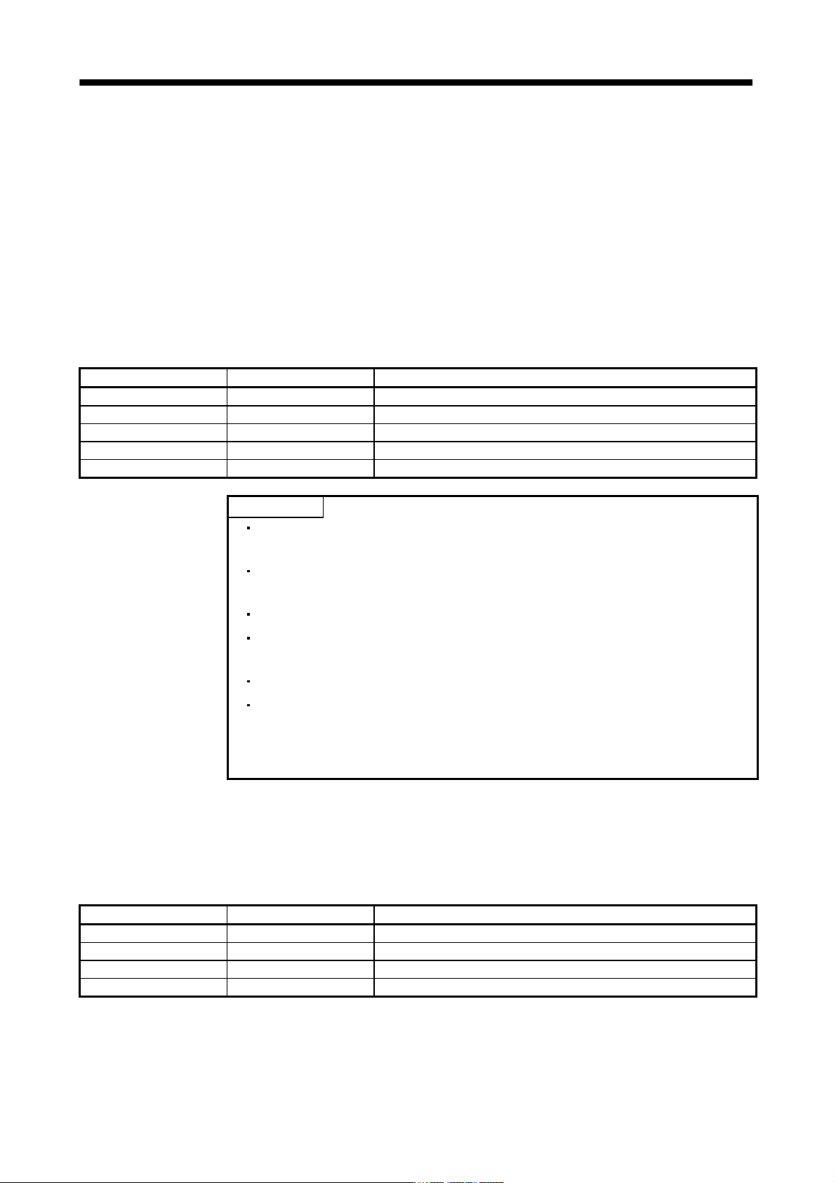
The following parameters are automatically adjusted in the auto tuning mode 1.
Parameter No. Abbreviation Name
PB06 GD2 Ratio of load inertia moment to servo motor inertia moment
PB07 PG1 Model loop gain
PB08 PG2 Position loop gain
PB09 VG2 Speed loop gain
PB10 VIC Speed integral compensation
POINT
The auto tuning mode 1 may not be performed properly if the following
conditions are not satisfied.
Time to reach 2000r/min is the acceleration/deceleration time constant of 5s or
less.
Speed is 150r/min or higher.
The ratio of load inertia moment to servo motor inertia moment is 100 times or
less.
The acceleration/deceleration torque is 10% or more of the rated torque.
Under operating conditions which will impose sudden disturbance torque
during acceleration/deceleration or on a machine which is extremely loose,
auto tuning may not function properly, either. In such cases, use the auto
tuning mode 2 or manual mode to make gain adjustment.
(2) Auto tuning mode 2
Use the auto tuning mode 2 when proper gain adjustment cannot be made by auto tuning mode 1. Since
the load inertia moment ratio is not estimated in this mode, set the value of a correct load inertia moment
ratio (parameter No.PB06).
The following parameters are automatically adjusted in the auto tuning mode 2.
Parameter No. Abbreviation Name
PB07 PG1 Model loop gain
PB08 PG2 Position loop gain
PB09 VG2 Speed loop gain
PB10 VIC Speed integral compensation