sh030051g.pdf - 第378页
13 - 77 13. SERVO AMPLIFIERS WI TH A LARGE CAPACITY ( 30k TO 55kW ) (b) MR-RB137 MR-RB138-4 POINT Three of MR-RB137 or MR-RB1 38-4 ar e required per conve rter unit. Please purchase three of MR-RB137 or MR-RB 138-4. RA (…
13 - 76
13. SERVO AMPLIFIERS WITH A LARGE CAPACITY
(
30k TO 55kW
)
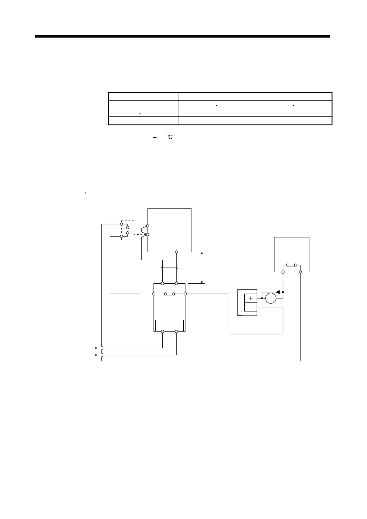
(4) Connection of the regenerative option
Always supply 1-phase 200V and 400V respectively to the cooling fan. The cooling fan specifications are as
follows.
Table 13.3 Cooling fan
Item 200V class 400V class
Model MR-RB137 MR-RB139 MR-RB136-4 MR-RB138-4
Voltage Frequency 1-phase 198 to 242VAC, 50/60Hz 1-phase 380 to 480VAC, 50/60Hz
Power consumption [W] 20 (50Hz)/18 (60Hz) 20 (50Hz)/18 (60Hz)
The regenerative option generates heat of
100 higher than the ambient temperature. Fully consider heat
dissipation, installation position, used wires, etc. to place the option. For wiring, use flame-resistant wires or
make the wires flame-resistant and keep them away from the regenerative option. The G3 and G4 terminals act
as a thermal sensor. G3-G4 are opened when the regenerative option overheats abnormally.
Always twist the wires for connection with the converter unit and connect the wires within the overall distance of
5m.
(a) MR-RB139
MR-RB136-4
Converter unit
P
1
P2
(Note 1)
Power factor improving
DC reactor (Option)
C
Servo motor
G4G3
PC
Regenerative
option
Cooling fan
RA
(Note 2)
5m or less
(Note 3)
Power supply
24VDC
power supply
Servo motor
thermal relay
OHS1 OHS2
RS
(Note 4)
Note 1. When using the Power factor improving DC reactor, remove the short bar across P1-P2.
2. G3-G4 contact specifications
Maximum voltage: 120V AC/DC
Maximum current: 0.5V/4.8VDC
Maximum capacity: 2.4VA
3. For specifications of cooling fan power supply, refer to Table 13.3.
4. For MR-RB136-4, “R” is “R400” and “S” is “S400”.
13 - 77
13. SERVO AMPLIFIERS WITH A LARGE CAPACITY
(
30k TO 55kW
)
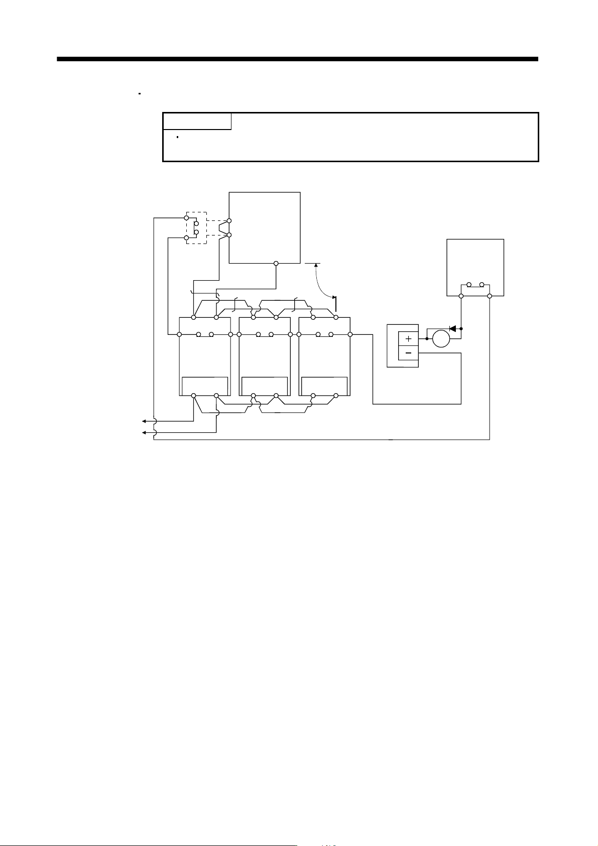
(b) MR-RB137
MR-RB138-4
POINT
Three of MR-RB137 or MR-RB138-4 are required per converter unit. Please
purchase three of MR-RB137 or MR-RB138-4.
RA
(Note 2)
CPCPCP
Regenerative
option
Converter unit
P
1
P2
(Note 1)
Power factor improving
DC reactor (Option)
C
Servo motor
G4G3
Cooling fan
5m or less
(Note 3)
Power supply
24VDC
power supply
Servo motor
thermal relay
OHS1 OHS2
RS
Regenerative
option
G4G3
Cooling fan
RS
Regenerative
option
G4G3
Cooling fan
RS
(Note 4)(Note 4) (Note 4)
Note 1. When using the Power factor improving DC reactor, remove the short bar across P1-P2.
2. G3-G4 contact specifications
Maximum voltage: 120V AC/DC
Maximum current: 0.5V/4.8VDC
Maximum capacity: 2.4VA
3. For specifications of cooling fan power supply, refer to Table 13.3.
4. For MR-RB138-4, “R” is “R400” and “S” is “S400”.
13 - 78
13. SERVO AMPLIFIERS WITH A LARGE CAPACITY
(
30k TO 55kW
)
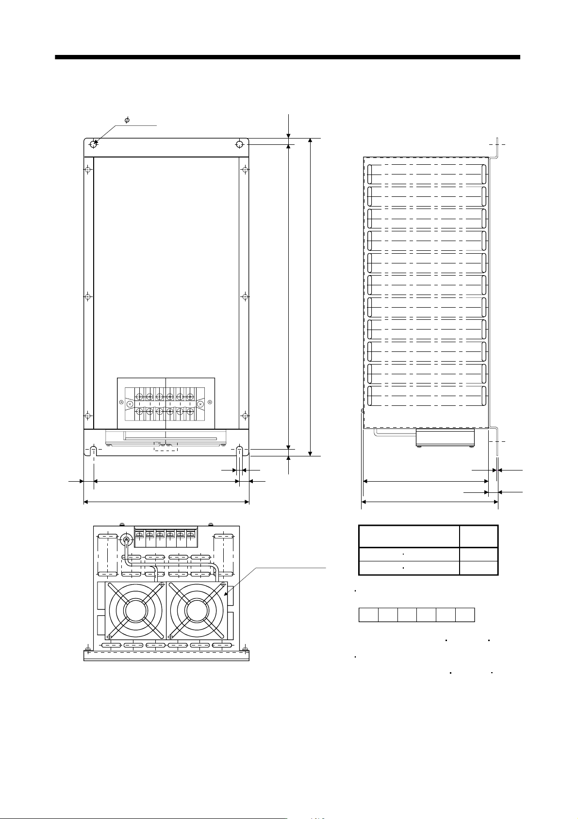
(5) Outline dimension drawings
[Unit:mm]
MR-RB139 MR-RB136-4
Mass
[kg(lb)]
11(24.25)
10(22.05)
10
15
15
TE1
10 480
500
10
10
2- 10 hole
Regenerative option
R
(Note 2)
G4 G3 C P
260
230
215
197
MR-RB137 MR-RB138-4
Terminal block signal layout
TE1
Terminal screw: M5
Tightening torque: 2.0 [N m] (17.7 [lb in])
Mounting screw
Screw size: M8
Tightening torque: 13.2 [N m] (117 [lb in])
2.3
15
S
(Note 2)
Cooling fan (Note 1)
Note 1. One cooling fan for MR-RB136-4, MR-RB138-4.
2. For MR-RB138-4, “R” is “R400” and “S” is “S400”.