sh030051g.pdf - 第167页
7 - 10 7. SPECIAL ADJUSTMENT FUNCTIONS 7.5 Low-pass filter (1) Function When a ball screw or the like is used, resonance of hi gh frequency may occur as the response level of the servo system is increased. To prevent thi…

7 - 9
7. SPECIAL ADJUSTMENT FUNCTIONS
POINT
When machine end vibration does not show up in motor end vibration, the
setting of the motor end vibration frequency does not produce an effect.
When the anti-resonance frequency and resonance frequency can be
confirmed using the machine analyzer or external FFT device, do not set the
same value but set different values to improve the vibration suppression
performance.
A vibration suppression control effect is not produced if the relationship
between the model loop gain (parameter No.PB07) value and vibration
frequency is as indicated below. Make setting after decreasing PG1, e.g.
reduce the response setting.
2
1
(1.5 PG1) vibration frequency

7 - 10
7. SPECIAL ADJUSTMENT FUNCTIONS
7.5 Low-pass filter
(1) Function
When a ball screw or the like is used, resonance of high frequency may occur as the response level of the
servo system is increased. To prevent this, the low-pass filter is factory-set to be valid for a torque
command. The filter frequency of this low-pass filter is automatically adjusted to the value in the following
expression.
Filter frequency(rad/s)
1 + GD2
VG2
10
When parameter No.PB23 is set to "
1 ", manual setting can be made with parameter No.PB18.
(2) Parameter
Set the operation of the low-pass filter selection (parameter No.PB23.)
Parameter No.PB23
Low-pass filter selection
0: Automatic setting (initial value)
1: Manual setting (parameter No.PB18 setting)
7.6 Gain changing function
This function can change the gains. You can change between gains during rotation and gains during stop or
can use an input device to change gains during operation.
7.6.1 Applications
This function is used when.
(1) You want to increase the gains during servo lock but decrease the gains to reduce noise during rotation.
(2) You want to increase the gains during settling to shorten the stop settling time.
(3) You want to change the gains using an input device to ensure stability of the servo system since the load
inertia moment ratio varies greatly during a stop (e.g. a large load is mounted on a carrier).
7 - 11
7. SPECIAL ADJUSTMENT FUNCTIONS
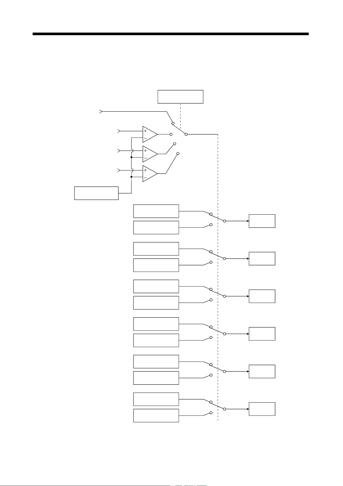
7.6.2 Function block diagram
The valid loop gains PG2, VG2, VIC and GD2 of the actual loop are changed according to the conditions
selected by gain changing selection CDP (parameter No.PB26) and gain changing condition CDS (parameter
No.PB27).
GD2
Parameter No.PB06
GD2B
Parameter No.PB29
PG2
Parameter No.PB08
PG2B
Parameter No.PB30
VG2
Parameter No.PB09
VG2B
Parameter No.PB31
VIC
Parameter No.PB10
VICB
Parameter No.PB32
CDS
Parameter No.PB27
VRF1
Parameter No.PB19
VRF1B
Parameter No.PB33
VRF2
Parameter No.PB20
VRF2B
Parameter No.PB34
Command pulse
frequency
Droop pulses
Model speed
Control
command of
controller
Comparator
Changing
Valid
GD2 value
Valid
PG2 value
Valid
VG2 value
Valid
VIC value
Valid
VRF1 value
Valid
VRF2 value
CDP
Parameter No.PB26