sh030051g.pdf - 第201页
10 - 6 10. CHARACTERISTIC S 10.3 Dynamic brake characteristics 10.3.1 Dynamic brake operation (1) Calculation of coasting distance Fig. 10.3 shows the pattern in which the servo motor comes to a stop when the dynamic bra…
10 - 5
10. CHARACTERISTICS
(2) Heat dissipation area for enclosed servo amplifier
The enclosed control box (hereafter called the control box) which will contain the servo amplifier should be
designed to ensure that its temperature rise is within
10 at the ambient temperature of 40 . (With a 5
(41
) safety margin, the system should operate within a maximum 55 (131 ) limit.) The necessary
enclosure heat dissipation area can be calculated by Equation 10.1.
P
A
KT
............................................................................................................................................. (10.1)
where, A : Heat dissipation area [m
2
]
P : Loss generated in the control box [W]
T : Difference between internal and ambient temperatures [ ]
K : Heat dissipation coefficient [5 to 6]
When calculating the heat dissipation area with Equation 10.1, assume that P is the sum of all losses
generated in the enclosure. Refer to Table 10.1 for heat generated by the servo amplifier. "A" indicates the
effective area for heat dissipation, but if the enclosure is directly installed on an insulated wall, that extra
amount must be added to the enclosure's surface area.
The required heat dissipation area will vary wit the conditions in the enclosure. If convection in the
enclosure is poor and heat builds up, effective heat dissipation will not be possible. Therefore, arrangement
of the equipment in the enclosure and the use of a cooling fan should be considered.
Table 10.1 lists the enclosure dissipation area for each servo amplifier when the servo amplifier is operated
at the ambient temperature of 40
(104 ) under rated load.
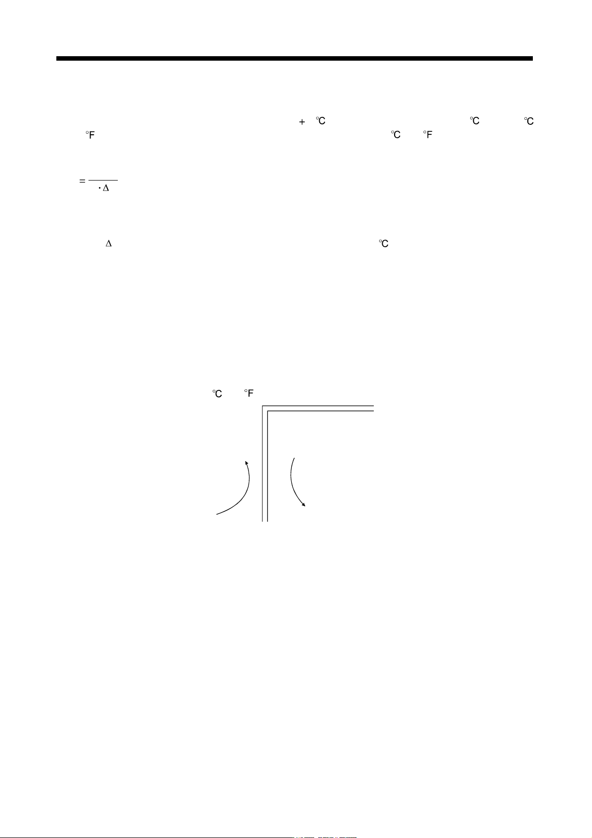
(Outside)
(Inside)
Air flow
Fig. 10.2 Temperature distribution in enclosure
When air flows along the outer wall of the enclosure, effective heat exchange will be possible, because the
temperature slope inside and outside the enclosure will be steeper.
10 - 6
10. CHARACTERISTICS
10.3 Dynamic brake characteristics
10.3.1 Dynamic brake operation
(1) Calculation of coasting distance
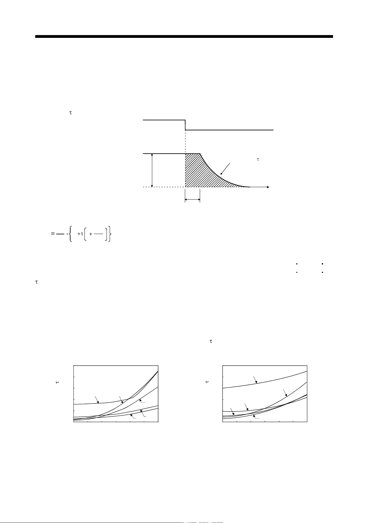
Fig. 10.3 shows the pattern in which the servo motor comes to a stop when the dynamic brake is operated.
Use Equation 10.2 to calculate an approximate coasting distance to a stop. The dynamic brake time
constant
varies with the servo motor and machine operation speeds. (Refer to (2)(a), (b) of this section.)
V
0
Time constant
Forced stop(EM1)
OFF
ON
Machine speed
t
e
Time
Fig. 10.3 Dynamic brake operation diagram
Lmax
60
V
0
JL
JM
t
e
1
....................................................................................................................... (10.2)
L
max : Maximum coasting distance .................................................................................................... [mm][in]
Vo : Machine rapid feed rate .............................................................................................. [mm/min][in/min]
J
M
: Servo motor inertial moment ..................................................................................... [kg cm
2
][oz in
2
]
J
L
: Load inertia moment converted into equivalent value on servo motor shaft ............ [kg cm
2
][oz in
2
]
: Brake time constant .......................................................................................................................... [s]
t
e
: Delay time of control section ............................................................................................................. [s]
For 7kW or less servo, there is internal relay delay time of about 30ms. For 11k to 22kW servo,
there is delay time of about 100ms caused by a delay of the external relay and a delay of the
magnetic contactor built in the external dynamic brake.
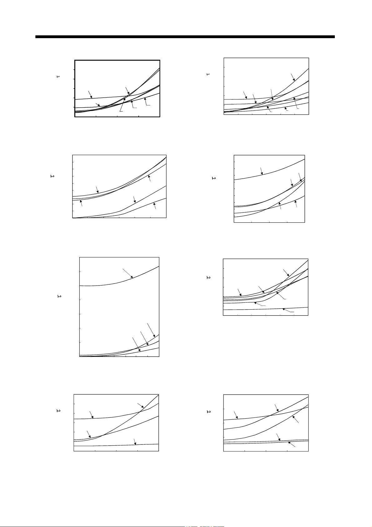
(2) Dynamic brake time constant
The following shows necessary dynamic brake time constant
for the equations (10.2).
(a) 200V class servo motor
Speed [r/min]
0
0 1000 2000
5
10
15
20
25
3000 4000 5000 6000
43
053
13
2373
Time constant [ms]
0
0 1000 2000
5
10
15
20
25
3000 4000 5000 6000
43
053
13
23
73
Speed [r/min]
Time constant [ms]
HF-MP series HF-KP series
10 - 7
10. CHARACTERISTICS
Speed [r/min]
T
i
m
e
c
o
n
s
t
a
n
t
[
m
s
]
500 1000 1500 2000
10
20
30
40
50
60
0
0
81
201
121
51
421
301
Speed [r/min]
Time constant [ms]
52
500 1000
1500 2000 2500 3000
152
20
40
60
80
100
120
0
0
102
202
502
702
352
HF-SP1000r/min series HF-SP2000r/min series
Speed [r/min]
0
2
4
6
8
10
12
14
16
18
0 500 1000 1500 2000 2500 3000
153
503
103
353
203
Ti
m
e
c
o
n
s
t
a
n
t
[
m
s
]
Speed [r/min]
352
500 1000 1500 20000
0
10
20
30
40
50
60
70
80
90
100
502
72
202
152
Ti
m
e
c
o
n
s
t
a
n
t
[
m
s
]
HC-RP series HC-UP2000r/min series
0
10
20
30
40
50
60
50 500 100015002000250030000
43
23
70
13
73
Speed
[r/min]
Ti
m
e
c
o
n
s
t
a
n
t
[
m
s
]
Speed[r/min]
200 400 600 1200
Ti
m
e
c
o
n
s
t
a
n
t
[
m
s
]
10
20
30
40
50
60
0
0
800 1000
15K1
25K1
12K1
801
20K1
601
HC-UP3000r/min HA-LP1000r/min series
0
Speed[r/min]
20
40
60
80
100
120
0 500 1000 1500 2000
11K1M
15K1M
22K1M
701M
Ti
m
e
c
o
n
s
t
a
n
t
[
m
s
]
Speed[r/min]
0
0
500
1000 1500 2000
80
60
40
20
11K2
15K2
22K2
502
702
Ti
m
e
c
o
n
s
t
a
n
t
[
m
s
]
HA-LP1500r/min series HA-LP2000r/min series