sh030051g.pdf - 第78页
3 - 23 3. SIGNALS AND WI RING 3.4 Connectors and si gnal arrangements POINT The pin configurations of the conne cto rs are as viewed from the cable connector wiring se ction. (1) Signal arrangement The servo amplifier fr…
3 - 22
3. SIGNALS AND WIRING
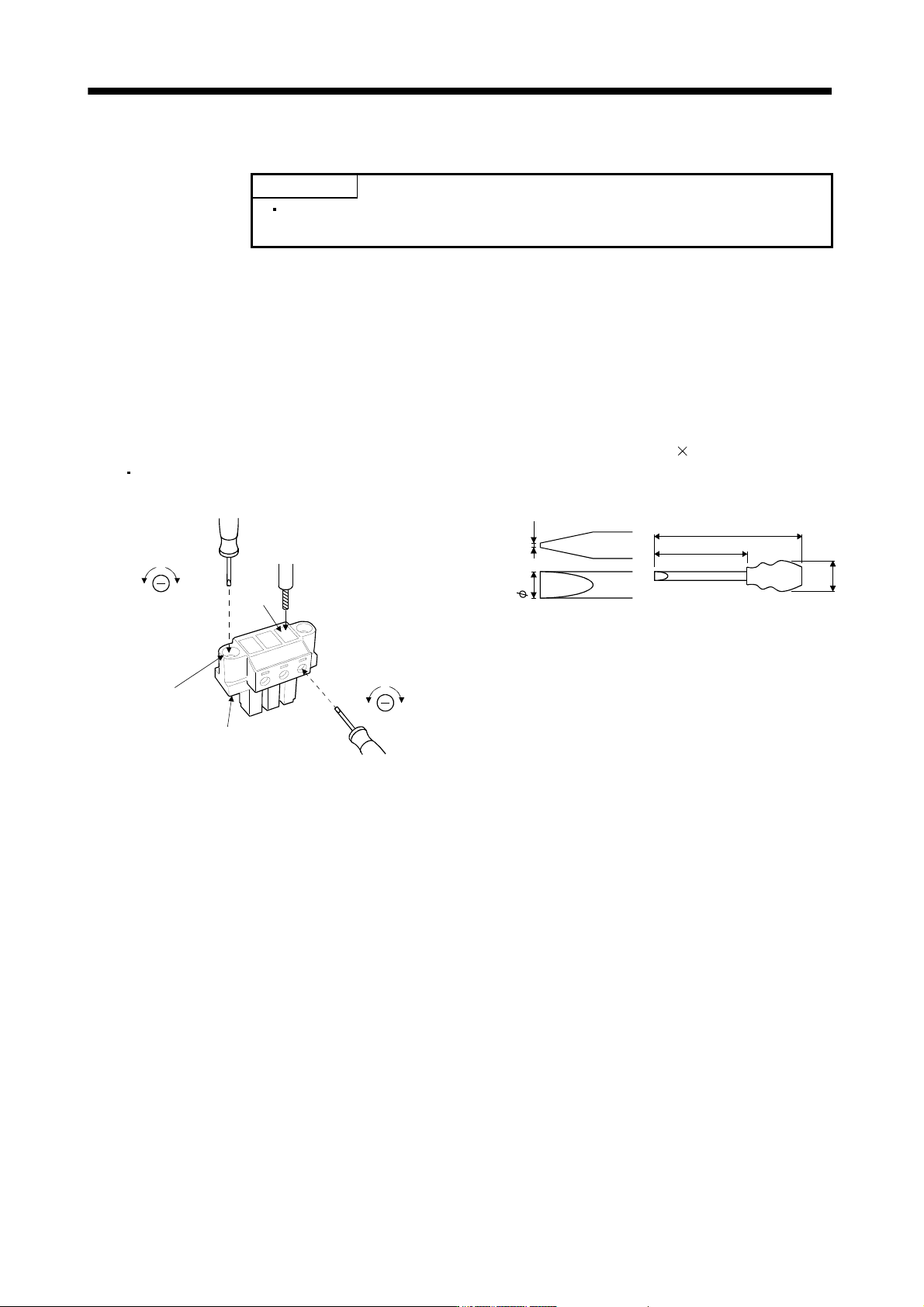
(4) How to insert the cable into Phoenix Contact connector
POINT
Do not use a precision driver because the cable cannot be tightened with
enough torque.
Insertion of cables into Phoenix Contact connector PC4/6-STF-7.62-CRWH or PC4/3-STF-7.62-CRWH is
shown as follows.
Before inserting the cable into the opening, make sure that the screw of the terminal is fully loose. Insert the
core of the cable into the opening and tighten the screw with a flat-blade screwdriver. When the cable is not
tightened enough to the connector, the cable or connector may generate heat because of the poor contact.
(When using a cable of 1.5mm2 or less, two cables may be inserted into one opening.)
Secure the connector to the servo amplifier by tightening the connector screw.
For securing the cable and the connector, use a flat-blade driver with 0.6mm blade edge thickness and
3.5mm diameter (Recommended flat-blade screwdriver: Phoenix Contact SZS 0.6
3.5). Apply 0.5 to 0.6
N
m torque to screw.
[Unit: mm]
Flat-blade
screwdriver
To loosen To tighten
Wire
Opening
To loosen To tighten
Flat-blade
screwdriver
Connector screw
Servo amplifier power
supply connector
3.5 0.6
180
100
(35)
Recommended flat-blade screwdriver dimensions
3 - 23
3. SIGNALS AND WIRING
3.4 Connectors and signal arrangements
POINT
The pin configurations of the connectors are as viewed from the cable
connector wiring section.
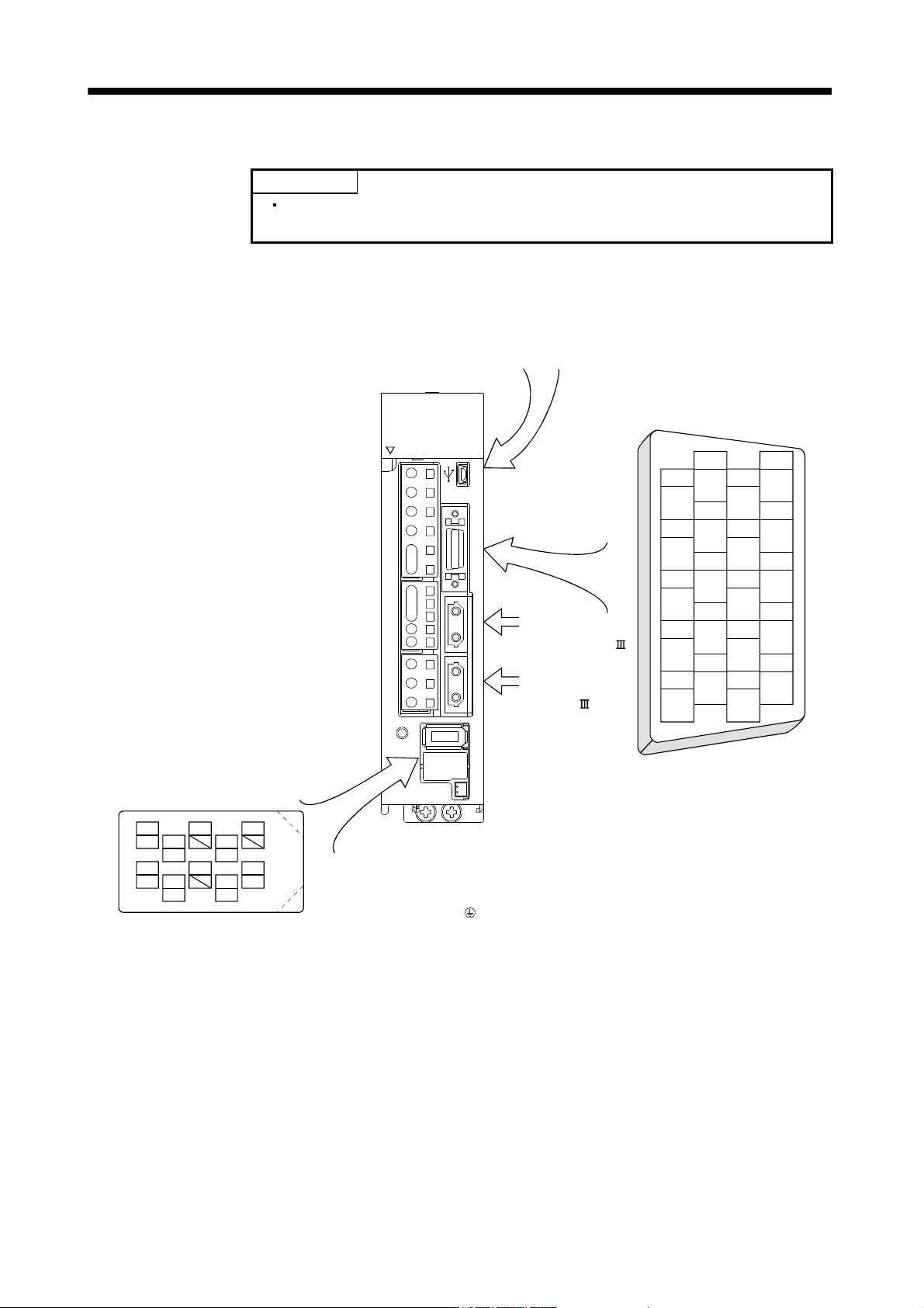
(1) Signal arrangement
The servo amplifier front view shown is that of the MR-J3-20B or less. Refer to chapter 9 Outline Drawings
for the appearances and connector layouts of the other servo amplifiers.
The 3M make connector is shown.
When using any other connector,
refer to section 11.1.2.
9
4
MRR
2
LG
8
6
1
P5
5
10
3
MR
7
BAT
CN2
MDR
MD
CN4 CN2L CN2 CN1B CN1A CN3 CN5
CHARGE
L
2
U
W
V
D
L
12
L11
C
P
N
P
1
P
2
L
3
L
1
OPEN
CN5 (USB connector)
Refer to section 11.8.
CN3
The frames of the CN2 and CN3
connectors are connected to the
PE (earth) terminal ( ) in the
amplifier.
Connector for
the front axis of
CN1A SSCNET
cable.
Connector for the
rear axis of CN1B
SSCNET cable.
2
111
12
4
313
14
6
515
16
8
717
18
10
919
20
DI1
LG LG
DI2
MO1
DOCOM
MBR
MO2
LA
DICOM
ALM
LAR
LZ
LB LBR
LZR
DICOM
INP DI1
EM1
3 - 24
3. SIGNALS AND WIRING
3.5 Signal (device) explanations
For the I/O interfaces (symbols in I/O division column in the table), refer to section 3.7.2.
In the control mode field of the table
The pin No.s in the connector pin No. column are those in the initial status.
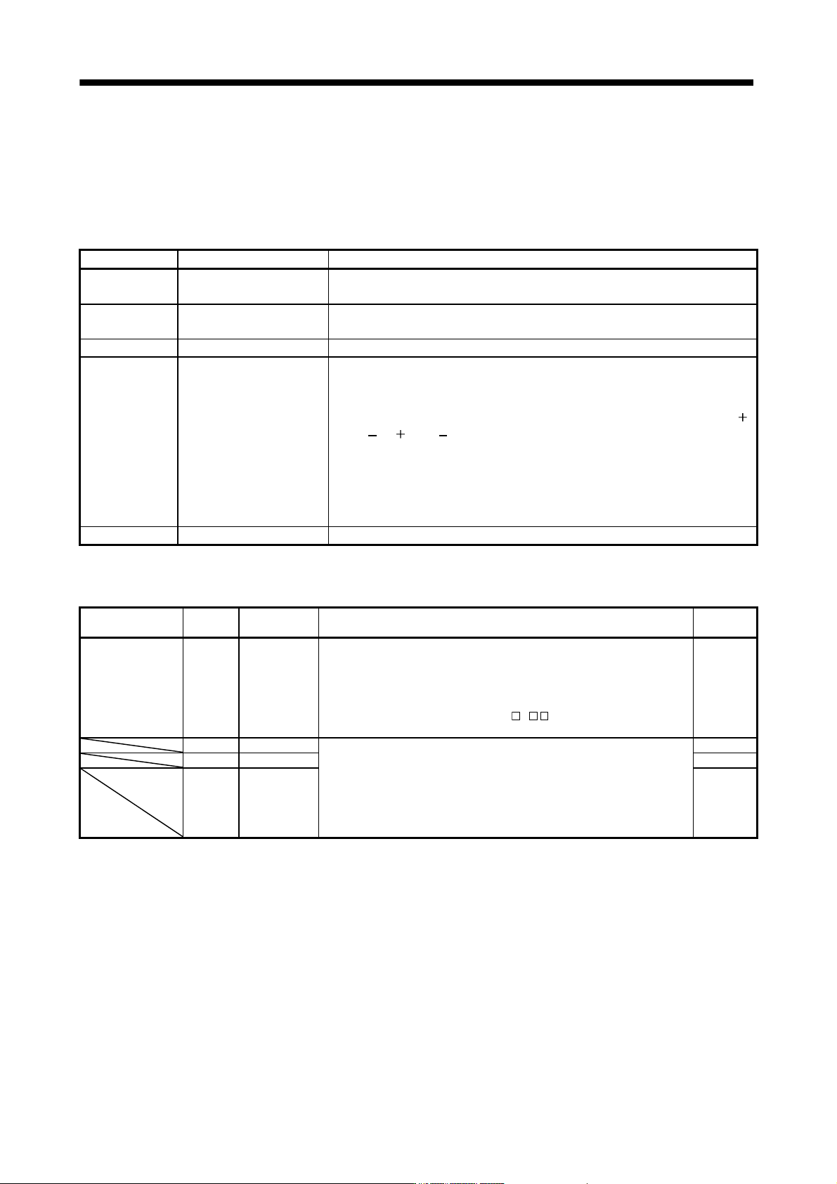
(1) Connector applications
Connector Name Function/Application
CN1A Connector for bus cable
from preceding axis.
Used for connection with the controller or preceding-axis servo amplifier.
CN1B Connector for bus cable to
next axis
Used for connection with the next-axis servo amplifier or for connection of the cap.
CN2 Encoder connector Used for connection with the servo motor encoder.
CN4 Battery connection
connector
When using as absolute position detection system, connect to battery (MR-J3BAT).
Before installing a battery, turn off the main circuit power while keeping the control
circuit power on. Wait for 15 minutes or more (20 minutes or for drive unit 30kW or
more) until the charge lamp turns off. Then, confirm that the voltage between P(
)
and N(
) (L and L for drive unit 30kW or more) is safe with a voltage tester and
others. Otherwise, an electric shock may occur. In addition, always confirm from the
front of the servo amplifier whether the charge lamp is off or not. Replace the
battery with main circuit power OFF and with control circuit power ON. Replacing
the battery with the control circuit power OFF results in loosing absolute position
data.
CN5 Communication connector The personal computer is connected.
(2) I/O device
(a) Input device
Device Symbol
Connector
pin No.
Function/Application
I/O
division
Forced stop EM1 CN3-20 Turn EM1 off (open between commons) to bring the motor to an forced
stop state, in which the base circuit is shut off and the dynamic brake is
operated.
Turn EM1 on (short between commons) in the forced stop state to reset
that state.
When parameter No.PA.04 is set to "
1 ", automatically ON
(always ON) can be set inside.
DI-1
DI1 CN3-2 Devices can be assigned for DI1 DI2 DI3 with controller setting.
For devices that can be assigned, refer to the controller instruction
manual. The following devices can be assigned for Q172HCPU
Q173HCPU QD75MH.
DI1: upper stroke limit (FLS)
DI2: lower stroke limit (RLS)
DI3: proximity dog (DOG)
DI-1
DI2 CN3-12 DI-1
DI3 CN3-19 DI-1