sh030051g.pdf - 第254页
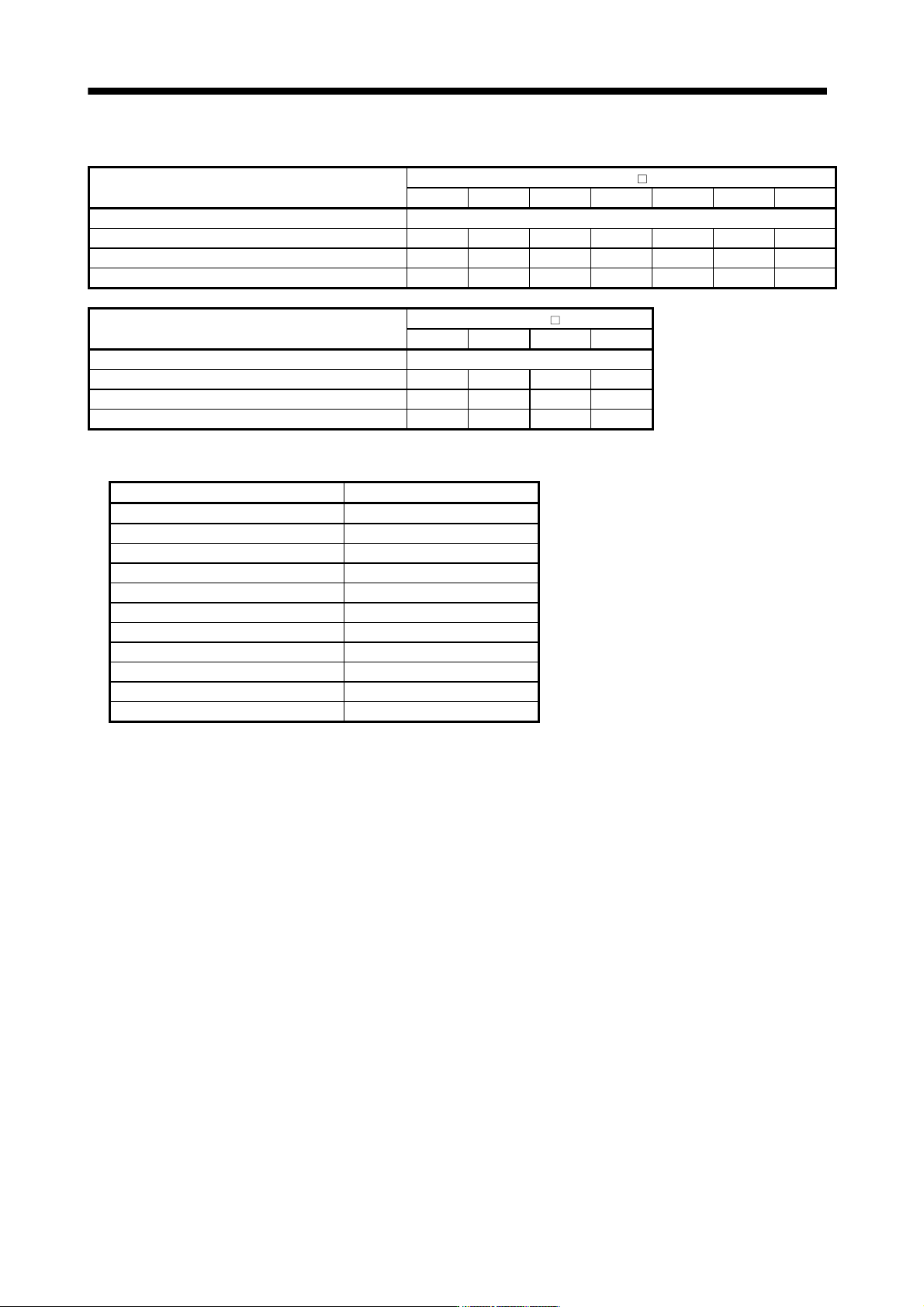
11 - 49 11. OPTIONS AND AUXILI ARY EQUIPMENT The following table lists the restrictions. Item FR-CV- 7.5K 11K 15K 22K 30K 37K 55K Maximum number of connected servo amplifiers 6 Total of connectable servo amplifier c apac…
11 - 48
11. OPTIONS AND AUXILIARY EQUIPMENT
11.5 Power regeneration common converter
POINT
Use the FR-CV for the servo amplifier of 200V class and the FR-CV-H for that
of 400V class.
For details of the power regeneration common converter FR-CV-(H), refer to
the FR-CV-(H) Installation Guide (IB(NA)0600075).
Do not supply power to the main circuit power supply terminals (L
1
, L
2
, L
3
) of
the servo amplifier. Doing so will fail the servo amplifier and FR-CV-(H).
Connect the DC power supply between the FR-CV-(H) and servo amplifier
with correct polarity. Connection with incorrect polarity will fail the FR-CV-(H)
and servo amplifier.
Two or more FR-CV-(H)'s cannot be installed to improve regeneration
capability. Two or more FR-CV-(H)'s cannot be connected to the same DC
power supply line.
When using the power regeneration common converter, set parameter No.PA02 to "
01".
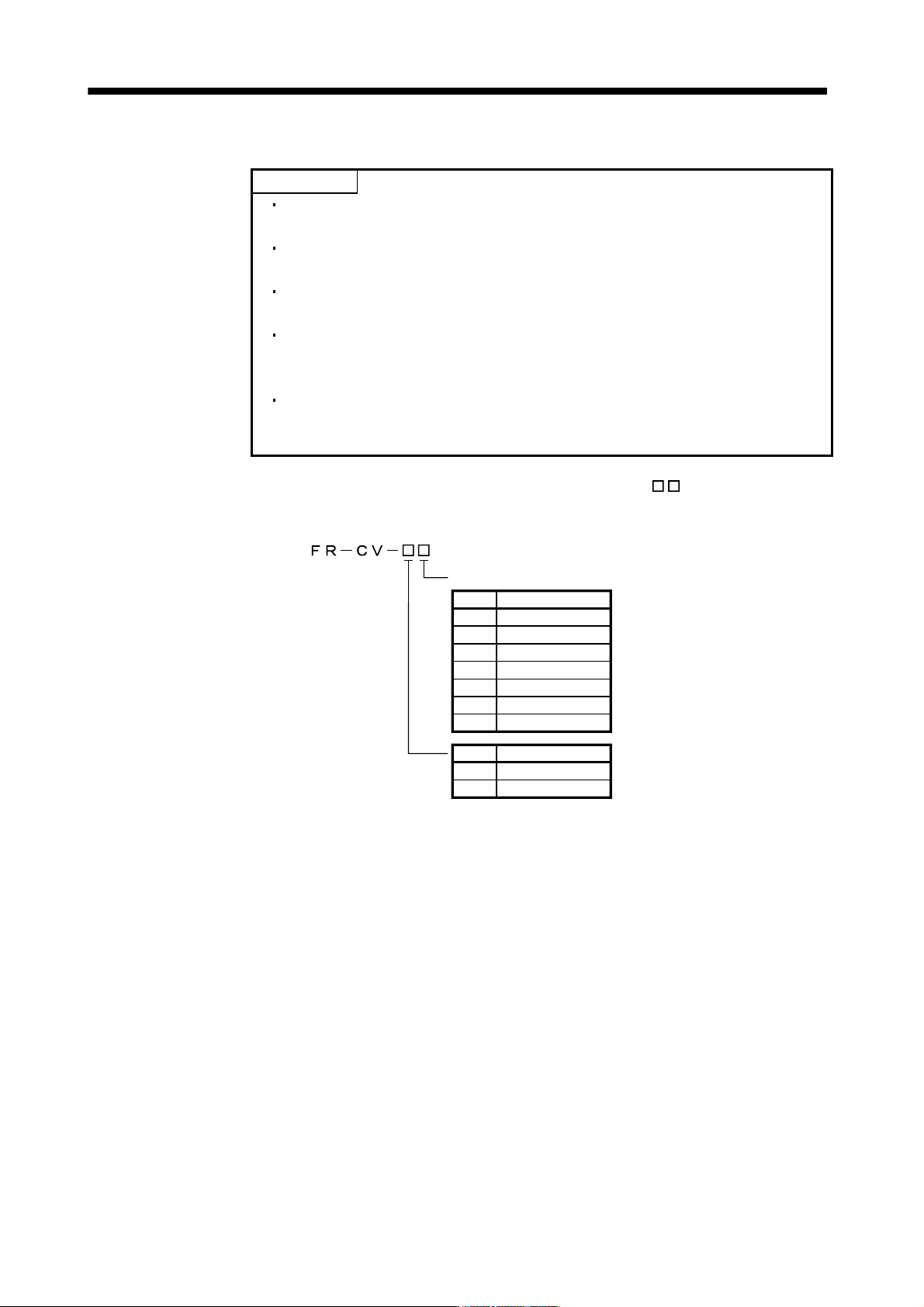
(1) Model
Symbol
Voltage class
None 200V class
H 400V class
Symbol
Capacity [kW]
7.5K 7.5
11K 11
15K 15
22K 22
30K 30
37K 37
55K 55
Capacity
(2) Selection
The power regenerative common converter FR-CV can be used for the servo amplifier of 200V class with
750 to 22kW and that of 400V class with 11k to 22kW. The following shows the restrictions on using the
FR-CV-(H).
(a) Up to six servo amplifiers can be connected to one FR-CV-(H).
(b) FR-CV-(H) capacity [W] Total of rated capacities [W] of servo amplifiers connected to FR-CV-(H) 2
(c) The total of used servo motor rated currents should be equal to or less than the applicable current [A] of
the FR-CV-(H).
(d) Among the servo amplifiers connected to the FR-CV-(H), the servo amplifier of the maximum capacity
should be equal to or less than the maximum connectable capacity [W].
11 - 49
11. OPTIONS AND AUXILIARY EQUIPMENT
The following table lists the restrictions.
Item
FR-CV-
7.5K 11K 15K 22K 30K 37K 55K
Maximum number of connected servo amplifiers 6
Total of connectable servo amplifier capacities [kW] 3.75 5.5 7.5 11 15 18.5 27.5
Total of connectable servo motor rated currents [A] 33 46 61 90 115 145 215
Maximum servo amplifier capacity [kW] 3.5 5 7 11 15 15 22
Item
FR-CV-H
22K 30K 37K 55K
Maximum number of connected servo amplifiers 6
Total of connectable servo amplifier capacities [kW] 11 15 18.5 27.5
Total of connectable servo motor rated currents [A] 90 115 145 215
Maximum servo amplifier capacity [kW] 11 15 15 22
When using the FR-CV-(H), always install the dedicated stand-alone reactor (FR-CVL-(H)).
Power regeneration common converter Dedicated stand-alone reactor
FR-CV-7.5K(-AT) FR-CVL-7.5K
FR-CV-11 K(-AT) FR-CVL-11 K
FR-CV-15K(-AT) FR-CVL-15K
FR-CV-22K(-AT) FR-CVL-22K
FR-CV-30K(-AT) FR-CVL-30K
FR-CV-37K FR-CVL-37K
FR-CV-55K FR-CVL-55K
FR-CV-H22K(-AT) FR-CVL-H22K
FR-CV-H30K(-AT) FR-CVL-H30K
FR-CV-H37K FR-CVL-H37K
FR-CV-H55K FR-CVL-H55K
11 - 50
11. OPTIONS AND AUXILIARY EQUIPMENT
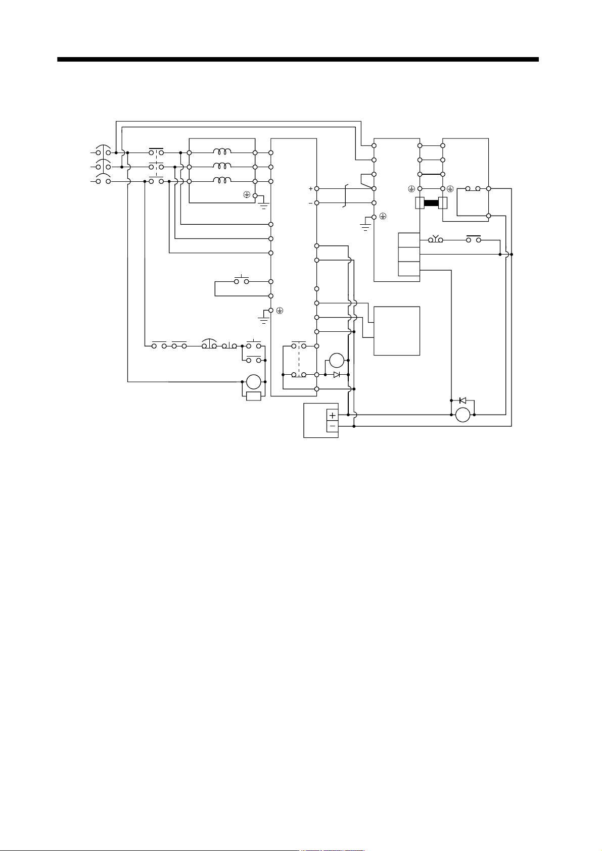
(3) Connection diagram
(a) 200V class
P
1
DOCOM
RA1
EM1
C
B
R/L11
3-phase
200 to
230VAC
S/L
21
T/L
31
R2/L1
S2/L
22
R2/L12
T2/L
32
S2/L2
(Note 3)
P24
SD
RDYB
RDYA
RSO
SE
A
T2/L
3
R/L
11
S/L
21
T/MC1
RES
SD
(Note 1)
L
11
L
21
P
N
U
V
W
(Note 1)
EM1
(Note 2)
RA1
RA2
24VDC
power
supply
Thermal
relay
OHS2
OHS1
CN2
MC
NF
FR-CVL FR-CV
MC
RA1 RA2
EM1
OFF
ON
RESET
SK
MC
(Note 1)
Servo motorServo amplifier
(Note 4)
Servo system
controller
(Note 5)
(Note 1)
(Note 7)
DICOM
N/L
P/L
U
V
W
(Note 6)
Note 1. Configure a sequence that will shut off main circuit power at an emergency stop or at FR-CV or servo amplifier alarm
occurrence.
2. For the servo motor with thermal relay, configure a sequence that will shut off main circuit power when the thermal relay
operates.
3. For the servo amplifier, configure a sequence that will switch the servo on after the FR-CV is ready.
4. For the FR-CV, the RSO signal turns off when it is put in a ready-to-operate status where the reset signal is input.
Configure a sequence that will make the servo inoperative when the RSO signal is on.
5. Configure a sequence that will make a stop with the emergency stop input of the servo system controller if an alarm occurs in
the FR-CV. When the servo system controller does not have an emergency stop input, use the forced stop input of the servo
amplifier to make a stop as shown in the diagram.
6. When using the servo amplifier of 7kW or less, make sure to disconnect the wiring of built-in regenerative resistor (3.5kW or
less: P and D, 5k/7kW: P and C).
7. When using the servo amplifier of 11k to 22kW, make sure to connect P
1 and P. (Factory-wired.)