sh030051g.pdf - 第178页
8 - 5 8. TROUBLESHOOTING Display Name Definition Cause Action 33 Overvoltage The following shows the input value of converter bus voltage. MR-J3- B(1): 400VDC or more MR-J3- B4: 800VDC or more 1. Regenerative option is n…
8 - 4
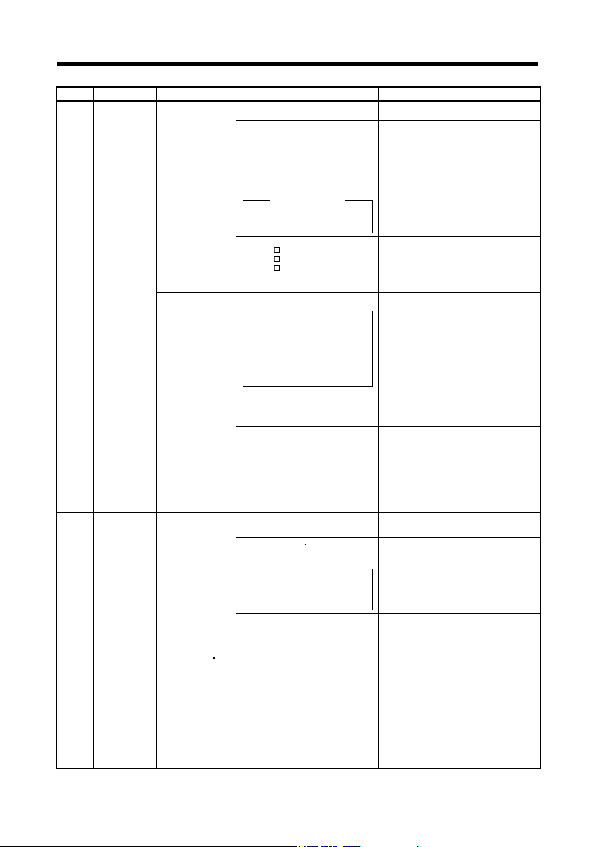
8. TROUBLESHOOTING
Display Name Definition Cause Action
30 Regenerative
error
Permissible
regenerative power
of the built-in
regenerative resistor
or regenerative
option is exceeded.
1. Wrong setting of parameter No.
PA02
Set correctly.
2. Built-in regenerative resistor or
regenerative option is not
connected.
Connect correctly.
3. High-duty operation or continuous
regenerative operation caused the
permissible regenerative power of
the regenerative option to be
exceeded.
Checking method
Call the status display and check
the regenerative load ratio.
1. Reduce the frequency of positioning.
2. Use the regenerative option of larger
capacity.
3. Reduce the load.
4. Power supply voltage is abnormal.
MR-J3-
B:260VAC or more
MR-J3-
B1:More than 135VAC
MR-J3-
B4: 535VAC or more
Check the power supply.
5. Built-in regenerative resistor or
regenerative option faulty.
Change the servo amplifier or regenerative
option.
Regenerative
transistor fault
6. Regenerative transistor faulty.
Checking method
1) The regenerative option has
overheated abnormally.
2) The alarm occurs even after
removal of the built-in
regenerative resistor or
regenerative option.
Change the servo amplifier.
31 Overspeed Speed has exceeded
the instantaneous
permissible speed.
1. Small acceleration/deceleration time
constant caused overshoot to be
large.
Increase acceleration/deceleration time
constant.
2. Servo system is instable to cause
overshoot.
1. Re-set servo gain to proper value.
2. If servo gain cannot be set to proper
value.
1) Reduce load inertia moment ratio; or
2) Reexamine acceleration/
deceleration time constant.
3. Encoder faulty. Change the servo motor.
32 Overcurrent
Current that flew is
higher than the
permissible current of
the servo amplifier.
(If the alarm (32)
occurs again when
turning ON the servo
after resetting the
alarm by turning
OFF/ON the power
when the alarm (32)
first occurred, the
transistor (IPM
IGBT) of the servo
amplifier may be at
fault. In the case, do
not repeat to turn
OFF/ON the power.
Check the transistor
with the checking
method of “Cause
2”.)
1. Short occurred in servo motor power
(U, V, W).
Correct the wiring.
2. Transistor (IPM IGBT) of the servo
amplifier faulty.
Checking method
Alarm (32) occurs if power is
switched on after U,V and W are
disconnected.
Change the servo amplifier.
3. Ground fault occurred in servo
motor power (U, V, W).
Correct the wiring.
4. External noise caused the
overcurrent detection circuit to
misoperate.
Take noise suppression measures.
8 - 5
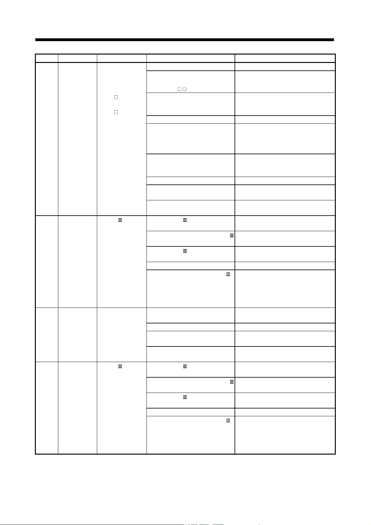
8. TROUBLESHOOTING
Display Name Definition Cause Action
33 Overvoltage The following shows
the input value of
converter bus
voltage.
MR-J3-
B(1):
400VDC or more
MR-J3-
B4:
800VDC or more
1. Regenerative option is not used. Use the regenerative option.
2. Though the regenerative option is
used, the parameter No.PA02
setting is " 00 (not used)".
Set correctly.
3. Lead of built-in regenerative resistor
or regenerative option is open or
disconnected.
1. Change the lead.
2. Connect correctly.
4. Regenerative transistor faulty. Change the servo amplifier.
5. Wire breakage of built-in
regenerative resistor or regenerative
option
1. For wire breakage of built-in regenerative
resistor, change the servo amplifier.
2. For wire breakage of regenerative option,
change the regenerative option.
6. Capacity of built-in regenerative
resistor or regenerative option is
insufficient.
Add regenerative option or increase
capacity.
7. Power supply voltage high. Check the power supply.
8. Ground fault occurred in servo
motor power (U, V, W).
Correct the wiring.
9. The jumper across BUE-SD of the
FR-BU2 brake unit is removed.
Fit the jumper across BUE-SD.
34 Receive error 1 SSCNET
communication error
(Continuously
communication error
with about 3.5ms
interval.)
1. The SSCNET
cable is
disconnected.
Connect it after turning off the control circuit
power supply for servo amplifier.
2. The surface at the end of SSCNET
cable got dirty.
Wipe dirt at the surface away. (Refer to
section 3.9)
3. The SSCNET cable is broken or
severed.
Change the cable.
4. Noise entered the servo amplifier. Take noise suppression measures.
5. Optical characteristic of SSCNET
cable deteriorated because vinyl
tape and/or wire sheath, which
contains migrating plasticizer,
adhered to the cable.
Remove the vinyl tape and/or wire sheath,
which contains migrating plasticizer, and
exchange the cable.
35 Command
frequency error
Input pulse frequency
of command pulse is
too high.
1. Command given is greater than the
maximum speed of the servo motor.
Check operation program.
2. Servo system controller failure. Change the servo system controller.
3. Noise entered the servo amplifier. Take noise of I/O signal suppression
measures.
4. Noise entered the controller. Take noise from the controller suppression
measures.
36 Receive error 2 SSCNET
communication error
(Intermittently
communication error
with about 70ms
interval.)
1. The SSCNET
cable is
disconnected.
Connect it after turning off the control circuit
power supply for servo amplifier.
2. The surface at the end of SSCNET
cable got dirty.
Wipe dirt away from the surface. (Refer to
section 3.9)
3. The SSCNET cable is broken or
severed.
Change the cable.
4. Noise entered the servo amplifier. Take noise suppression measures.
5. Optical characteristic of SSCNET
cable deteriorated because vinyl
tape and/or wire sheath, which
contains migrating plasticizer,
adhered to the cable.
Remove the vinyl tape and/or wire sheath,
which contains migrating plasticizer, and
exchange the cable.
8 - 6
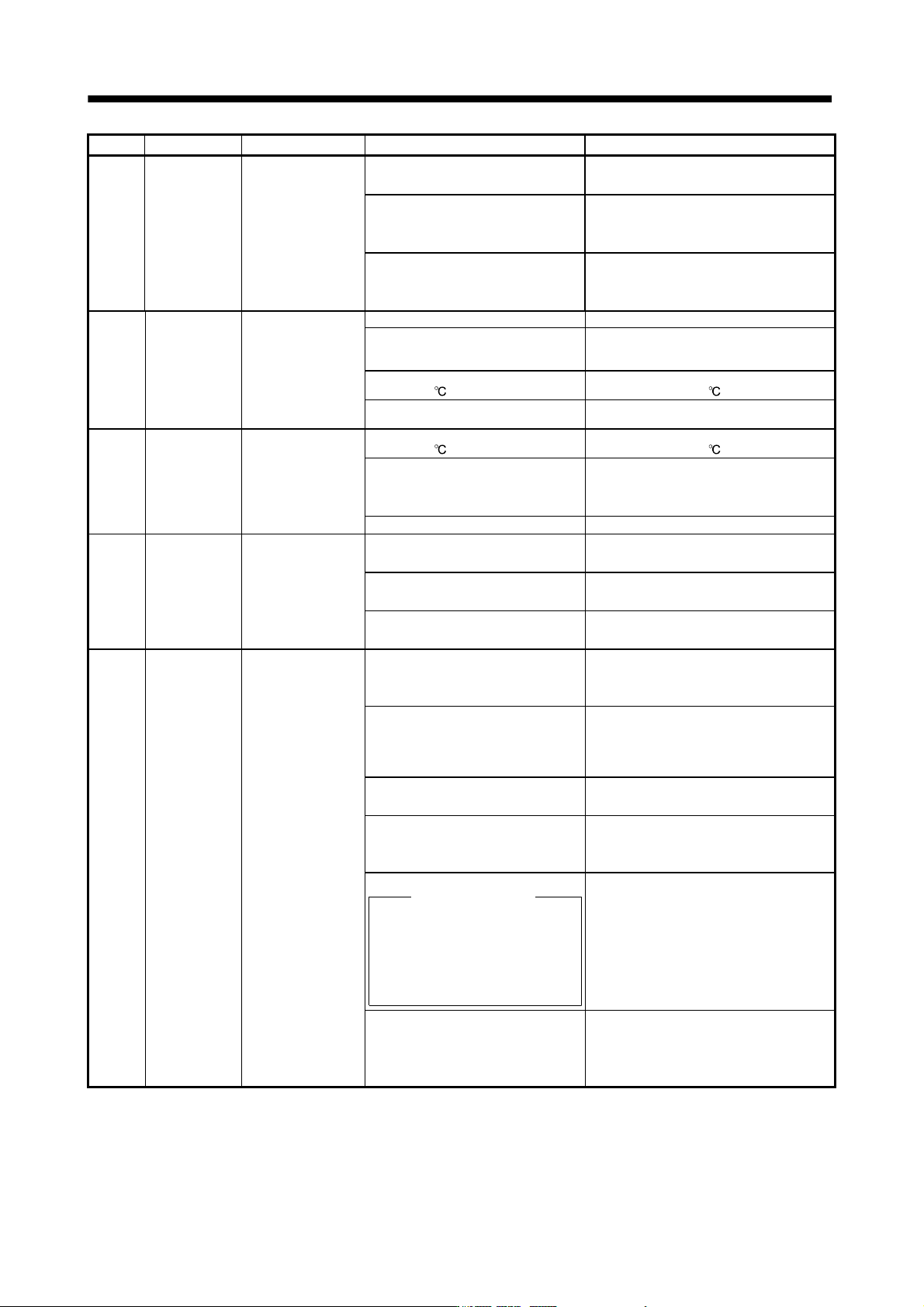
8. TROUBLESHOOTING
Display Name Definition Cause Action
37 Parameter error Parameter setting is
wrong.
1. Servo amplifier fault caused the
parameter setting to be rewritten.
Change the servo amplifier.
2. There is a parameter whose value
was set to outside the setting range
by the controller.
Change the parameter value to within the
setting range.
3. The number of write times to EEP-
ROM exceeded 100,000 due to
parameter write, etc.
Change the servo amplifier.
45 Main circuit
device overheat
Main circuit device
overheat
1. Servo amplifier faulty. Change the servo amplifier.
2. The power supply was turned on
and off continuously by overloaded
status.
The drive method is reviewed.
3. Ambient temperature of servo motor
is over 55
.
Check environment so that ambient
temperature is 0 to 55 .
4. Used beyond the specifications of
close mounting.
Use within the range of specifications.
46 Servo motor
overheat
Servo motor
temperature rise
actuated the thermal
sensor.
1. Ambient temperature of servo motor
is over 40
.
Check environment so that ambient
temperature is 0 to 40 .
2. Servo motor is overloaded. 1. Reduce load.
2. Check operation pattern.
3. Use servo motor that provides larger
output.
3. Thermal sensor in encoder is faulty. Change the servo motor.
47 Cooling fan
error
The cooling fan of
the servo amplifier
stopped, or its speed
decreased to or
below the alarm
level.
1. Cooling fan life expiration (Refer to
section 2.5.)
Change the cooling fan of the servo
amplifier.
2. Foreign matter caught in the cooling
fan stopped rotation.
Remove the foreign matter.
3. The power supply of the cooling fan
failed.
Change the servo amplifier.
50 Overload 1 Load exceeded
overload protection
characteristic of
servo amplifier.
1. Servo amplifier is used in excess
of its continuous output current.
1. Reduce load.
2. Check operation pattern.
3. Use servo motor that provides larger
output.
2. Servo system is instable and
hunting.
1. Repeat acceleration/
deceleration to execute auto tuning.
2. Change the auto tuning response setting.
3. Set auto tuning to OFF and make gain
adjustment manually.
3. Machine struck something. 1. Check operation pattern.
2. Install limit switches.
4. Wrong connection of servo motor.
Servo amplifier's output terminals U,
V, W do not match servo motor's
input terminals U, V, W.
Connect correctly.
5. Encoder faulty.
Checking method
When the servo motor shaft is
rotated with the servo off, the
cumulative feedback pulses do not
vary in proportion to the rotary angle
of the shaft but the indication skips
or returns midway.
Change the servo motor.
6. After Overload 2 (51) occurred, turn
OFF/ON the power supply to clear
the alarm. Then the overload
operation is repeated.
1. Reduce load.
2. Check operation pattern.
3. Use servo motor that provides larger
output.