sh030051g.pdf - 第174页
8 - 1 8. TROUBLESHOOTING 8. TROUBLESHOOTING POINT As soon as an alarm occurs, make the Servo off stat us and interrupt the main circuit power. If an alarm/warning has occurred, refer to this chapter and remove its cause.…
7 - 16
7. SPECIAL ADJUSTMENT FUNCTIONS
MEMO
8 - 1
8. TROUBLESHOOTING
8. TROUBLESHOOTING
POINT
As soon as an alarm occurs, make the Servo off status and interrupt the main
circuit power.
If an alarm/warning has occurred, refer to this chapter and remove its cause.
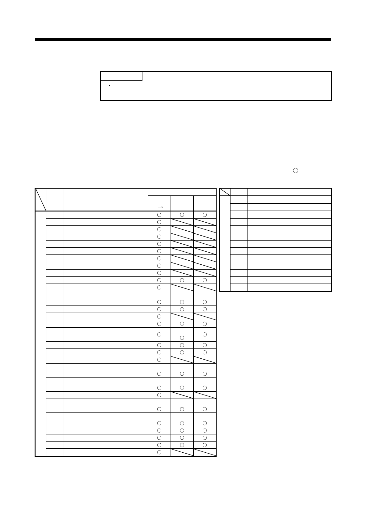
8.1 Alarms and warning list
When a fault occurs during operation, the corresponding alarm or warning is displayed. If any alarm or warning
has occurred, refer to section 8.2 or 8.3 and take the appropriate action. When an alarm occurs, the ALM turns
OFF.
After its cause has been removed, the alarm can be deactivated in any of the methods marked
in the alarm
deactivation column. The alarm is automatically canceled after removing the cause of occurrence.
Alarm deactivation Display Name
Display Name Power Error CPU
Warnings
92 Battery cable disconnection warning
OFF ON reset reset 96 Home position setting warning
Alarms
10 Undervoltage 9F Battery warning
12 Memory error 1 (RAM) E0 Excessive regeneration warning
13 Clock error E1 Overload warning 1
15 Memory error 2 (EEP-ROM) E3 Absolute position counter warning
16 Encoder error 1 (At power on) E4 Parameter warning
17 Board error E6 Servo forced stop warning
19 Memory error 3 (Flash-ROM) E7 Controller forced stop warning
1A Motor combination error E8 Cooling fan speed reduction warning
20 Encoder error 2 E9 Main circuit off warning
24 Main circuit error EC Overload warning 2
25 Absolute position erase ED Output watt excess warning
30 Regenerative error
(Note 1)
(Note 1)
(Note 1)
31 Overspeed
32 Overcurrent
33 Overvoltage
34 Receive error 1
(Note 2)
35 Command frequency error
36 Receive error 2
37 Parameter error
45 Main circuit device overheat
(Note 1)
(Note 1)
(Note 1)
46 Servo motor overheat
(Note 1)
(Note 1)
(Note 1)
47 Cooling fan error
50 Overload 1
(Note 1)
(Note 1)
(Note 1)
51 Overload 2
(Note 1)
(Note 1)
(Note 1)
52 Error excessive
8A USB communication time-out error
8E USB communication error
888 Watchdog
Note 1. Deactivate the alarm about 30 minutes of cooling time after removing the cause of occurrence.
2. In some controller communication status, the alarm factor may not be removed.
8 - 2
8. TROUBLESHOOTING
8.2 Remedies for alarms
CAUTION
When any alarm has occurred, eliminate its cause, ensure safety, then reset the
alarm, and restart operation. Otherwise, injury may occur.
If an absolute position erase (25) occurred, always make home position setting
again. Not doing so may cause unexpected operation.
As soon as an alarm occurs, mark Servo-off and power off the main circuit and
control circuit.
POINT
When any of the following alarms has occurred, do not deactivate the alarm
and resume operation repeatedly. To do so will cause the servo amplifier/servo
motor to fail. Remove the cause of occurrence, and leave a cooling time of
more than 30 minutes before resuming operation. To protect the main circuit
elements, any of these servo alarms cannot be deactivated from the servo
system controller until the specified time elapses after its occurrence. Judging
the load changing condition until the alarm occurs, the servo amplifier
calculates this specified time automatically.
Regenerative error (30)
Overload 1 (50)
Overload 2 (51)
The alarm can be deactivated by switching power off, then on or by the error
reset command
CPU reset from the servo system controller. For details, refer
to section 8.1.
When an alarm occurs, the trouble (ALM) switches off and the dynamic brake is operated to stop the servo
motor. At this time, the display indicates the alarm No.
The servo motor comes to a stop. Remove the cause of the alarm in accordance with this section. Use the MR
Configurator to refer to a factor of alarm occurrence.
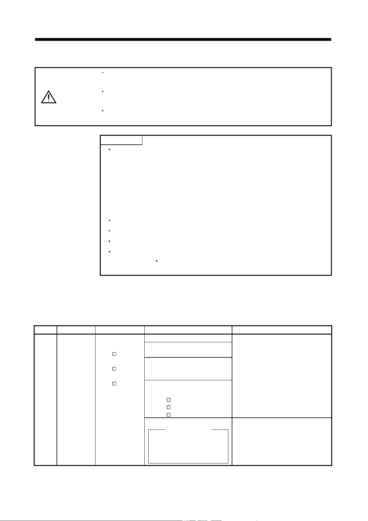
Display Name Definition Cause Action
10 Undervoltage Power supply voltage
dropped.
MR-J3-
B:
160VAC or less
MR-J3-
B1:
83VAC or less
MR-J3-
B4:
280VAC or less
1. Power supply voltage is low. Check the power supply.
2. There was an instantaneous control
power failure of 60ms or longer.
3. Shortage of power supply capacity
caused the power supply voltage to
drop at start, etc.
4. The bus voltage dropped to the
following value or less.
MR-J3-
B: 200VDC
MR-J3-
B1: 158VDC
MR-J3-
B4: 380VDC
5. Faulty parts in the servo amplifier
Checking method
Alarm (10) occurs if power is
switched on after disconnection
of all cables but the control
circuit power supply cables.
Change the servo amplifier.