sh030051g.pdf - 第41页
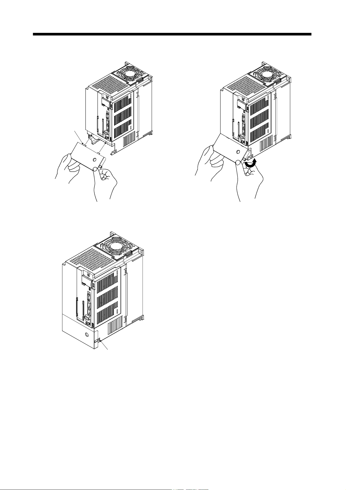
1 - 20 1. FUNCTIONS AND CONFIGURATIO N (2) For MR-J3-11KB(4) to MR-J3-22KB(4) Removal of the fron t cover A) B) C) 1) Press the removing knob on the lower side of the front cover ( A) and B) ) and release the in stallati…
1 - 19
1. FUNCTIONS AND CONFIGURATION
Reinstallation of the front cover
Front cover
setting tab
A)
A)
Insert the front cover setting tabs into the sockets of
servo amplifier (2 places).
Pull up the cover, supporting at point
A)
.
Setting tab
Push the setting tabs until they click.
1 - 20
1. FUNCTIONS AND CONFIGURATION
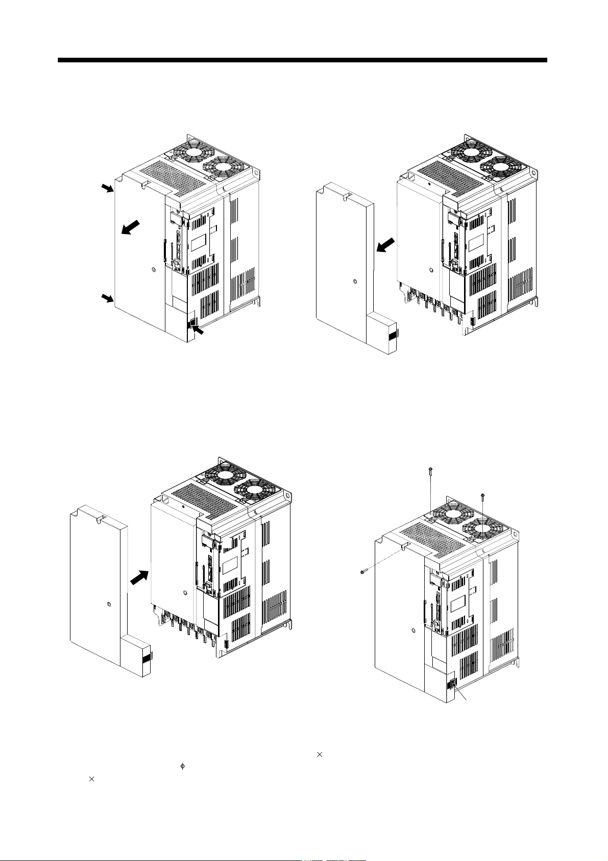
(2) For MR-J3-11KB(4) to MR-J3-22KB(4)
Removal of the front cover
A)
B)
C)
1) Press the removing knob on the lower side of the
front cover ( A) and B) ) and release the installation
hook.
2) Press the removing knob of C) and release the
external hook.
3) Pull it to remove the front cover.
Reinstallation of the front cover
A)
B)
C)
D)
Installation hoo
k
(Note 1)
(Note 1)
(Note 2)
1) Fit the front cover installation hooks on the sockets
of body cover ( A) to D) ) to reinstall it.
2) Push the front cover until you hear the clicking
noise of the installation hook.
Note 1. The cooling fan cover can be locked with enclosed screws (M4 40).
2. By drilling approximately
4 of a hole on the front cover, the front cover can be locked on the body with an enclosed screw (M4
14).
1 - 21
1. FUNCTIONS AND CONFIGURATION
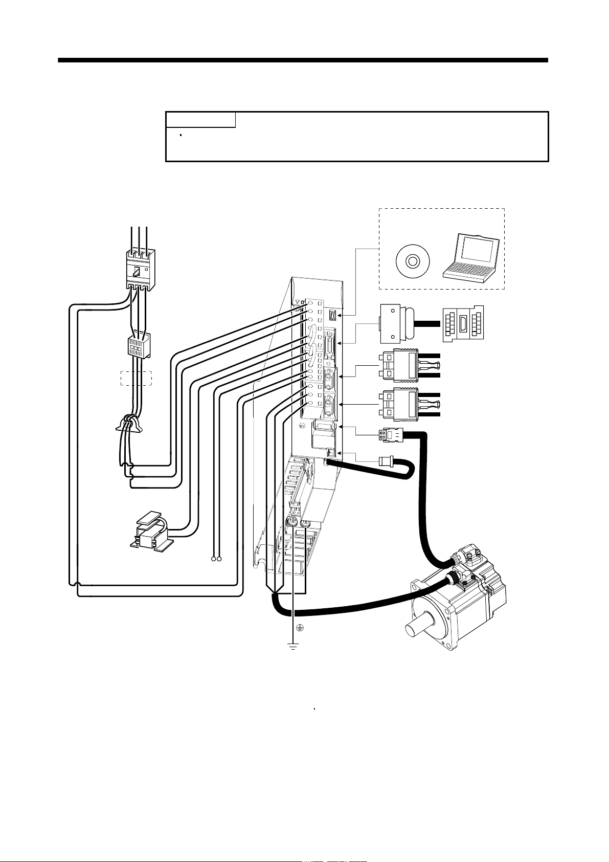
1.8 Configuration including auxiliary equipment
POINT
Equipment other than the servo amplifier and servo motor are optional or
recommended products.
(1) MR-J3-100B or less
(a) For 3-phase or 1-phase 200V to 230VAC
W
CN5
PC
L11
L
21
P1
P
2
UV
Servo amplifier
L
1
L
2
L3
MR Configurator
Personal
computer
Servo system
controller or Front axis
servo amplifier CN1B
Rear servo amplifier
CN1A or Cap
CN3
CN1A
CN1B
CN2
CN4
R S T
Line noise
filter
(FR-BSF01)
Magnetic
contactor
(MC)
No-fuse breaker
(NFB) or fuse
Regenerative option
Power factor
improving DC
reactor
(FR-BEL)
(Note 2)
(Note 2)
Junction terminal
block
Servo motor
(Note 1)
Battery
MR-J3BAT
(Note 3)
Power supply
Note 1. The battery (option) is used for the absolute position detection system in the position control mode.
2. The AC reactor can also be used. In this case, the DC reactor cannot be used. When not using DC reactor, short P
1 and P2.
3. A 1-phase 200V to 230VAC power supply may be used with the servo amplifier of MR-J3-70B or less.
For 1-phase 200V to 230VAC, connect the power supply to L
1 L2 and leave L3 open. Refer to section 1.3 for the power supply
specification.