sh030051g.pdf - 第284页
11 - 79 11. OPTIONS AND AUXILI ARY EQUIPMENT (b) Surge suppressor The recommended surge suppressor for installation to an AC relay, AC va lve or the like near the servo amplifier is shown below. Use this product or equiv…
11 - 78
11. OPTIONS AND AUXILIARY EQUIPMENT
Noise transmission route Suppression techniques
1) 2) 3)
When measuring instruments, receivers, sensors, etc. which handle weak signals and may malfunction
due to noise and/or their signal cables are contained in a control box together with the servo amplifier or
run near the servo amplifier, such devices may malfunction due to noises transmitted through the air. The
following techniques are required.
1. Provide maximum clearance between easily affected devices and the servo amplifier.
2. Provide maximum clearance between easily affected signal cables and the I/O cables of the servo
amplifier.
3. Avoid laying the power lines (Input cables of the servo amplifier) and signal cables side by side or
bundling them together.
4. Insert a line noise filter to the I/O cables or a radio noise filter on the input line.
5. Use shielded wires for signal and power cables or put cables in separate metal conduits.
4) 5) 6)
When the power lines and the signal cables are laid side by side or bundled together, magnetic
induction noise and static induction noise will be transmitted through the signal cables and malfunction
may occur. The following techniques are required.
1. Provide maximum clearance between easily affected devices and the servo amplifier.
2. Provide maximum clearance between easily affected signal cables and the I/O cables of the servo
amplifier.
3. Avoid laying the power lines (I/O cables of the servo amplifier) and signal cables side by side or
bundling them together.
4. Use shielded wires for signal and power cables or put the cables in separate metal conduits.
7)
When the power supply of peripheral devices is connected to the power supply of the servo amplifier
system, noises produced by the servo amplifier may be transmitted back through the power supply
cable and the devices may malfunction. The following techniques are required.
1. Insert the radio noise filter (
FR-BIF-(H)
) on the power cables (Input cables) of the servo amplifier.
2. Insert the line noise filter (FR-BSF01
FR-BLF) on the power cables of the servo amplifier.
8)
When the cables of peripheral devices are connected to the servo amplifier to make a closed loop
circuit, leakage current may flow to malfunction the peripheral devices. If so, malfunction may be
prevented by disconnecting the grounding cable of the peripheral device.
(2) Noise reduction products
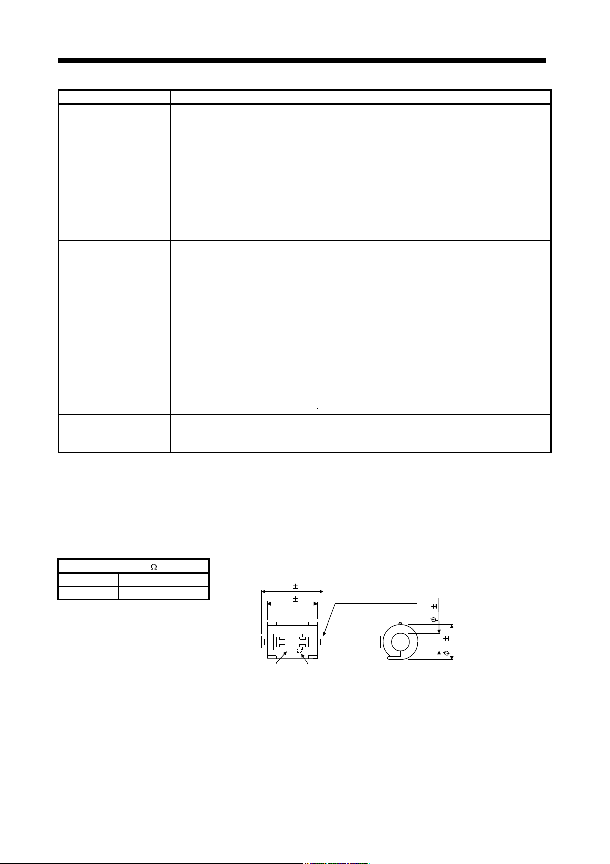
(a) Data line filter (Recommended)
Noise can be prevented by installing a data line filter onto the encoder cable, etc. For example, the
ZCAT3035-1330 of TDK and the ESD-SR-25 of NEC TOKIN make are available as data line filters. As a
reference example, the impedance specifications of the ZCAT3035-1330 (TDK) are indicated below.
This impedances are reference values and not guaranteed values.
Impedance[ ]
Outline drawing (ZCAT3035-1330)
[Unit: mm]
Loop for fixing the
cable band
Lot number Product name
TDK
39 1
34 1
1
3
1
3
0
1
10 to 100MHz 100 to 500MHz
80 150
11 - 79
11. OPTIONS AND AUXILIARY EQUIPMENT
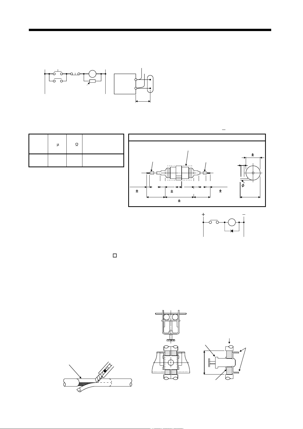
(b) Surge suppressor
The recommended surge suppressor for installation to an AC relay, AC valve or the like near the servo
amplifier is shown below. Use this product or equivalent.
MC
Surge suppressor
Relay
Surge suppresso
r
This distance should be short
(within 20cm).
(Ex.) 972A.2003 50411
(Matsuo Electric Co.,Ltd.
200VAC rating)
Rated
voltage
AC[V]
C [
F] R [ ] Test voltage AC[V]
Outline drawing [Unit: mm]
Blue vinyl cord
Red vinyl cord
Vinyl sheath
200 or more 200 or more
6
31
10 or less
10 or less
15 1
48 1.5
10 310 3
4
18 1.5
200 0.5
50
(1W)
Across
T-C 1000(1 to 5s)
Note that a diode should be installed to a DC relay, DC valve or
the like.
Maximum voltage: Not less than 4 times the drive voltage of the
relay or the like
Maximum current: Not less than twice the drive current of the
relay or the like
Diode
RA
(c) Cable clamp fitting AERSBAN -
SET
Generally, the earth of the shielded cable may only be connected to the connector's SD terminal.
However, the effect can be increased by directly connecting the cable to an earth plate as shown below.
Install the earth plate near the servo amplifier for the encoder cable. Peel part of the cable sheath to
expose the external conductor, and press that part against the earth plate with the cable clamp. If the
cable is thin, clamp several cables in a bunch.
The clamp comes as a set with the earth plate.
[Unit: mm]
Strip the cable sheath of
the clamped area.
cutter
cable
Cable clamp
(A,B)
Cable
Earth plate
External conductor
Clamp section diagram
4
0
11 - 80
11. OPTIONS AND AUXILIARY EQUIPMENT
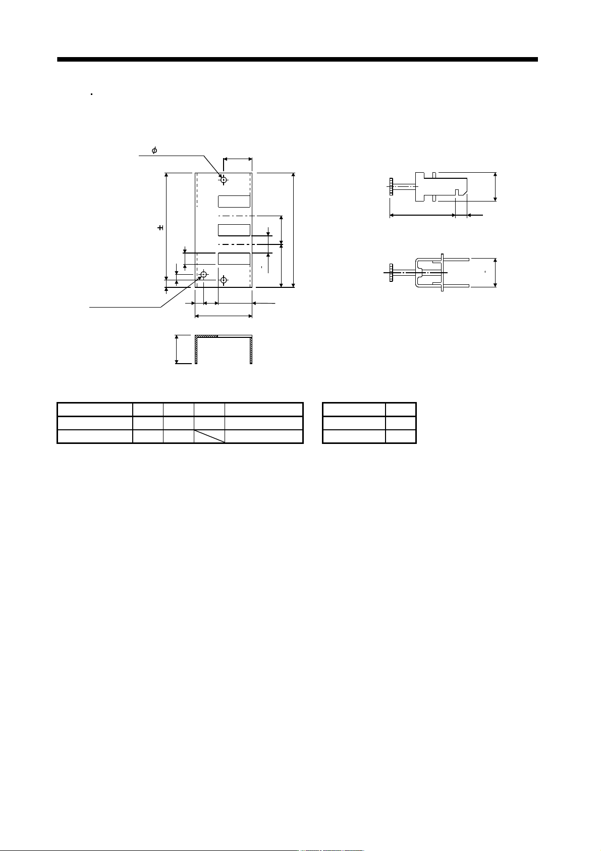
Outline drawing
[Unit: mm]
Earth plate Clamp section diagram
(Note)M4 screw
1
1
3
6
C
A
6
22
17.5
35
3
5
L or less
10
3
0
7
2
4
0
0
.
2
2
4
0
.
3
0
B
0
.
3
2- 5 hole
installation hole
Note. Screw hole for grounding. Connect it to the earth plate of the control box.
Type A B C Accessory fittings Clamp fitting L
AERSBAN-DSET 100 86 30 clamp A: 2pcs. A 70
AERSBAN-ESET 70 56 clamp B: 1pc. B 45