sh030051g.pdf - 第118页
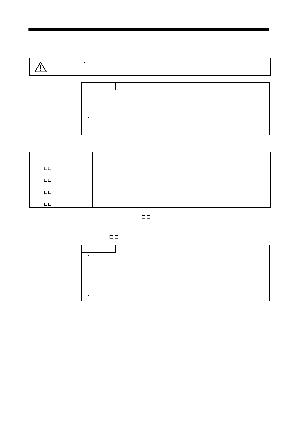
5 - 1 5. PARAMETERS 5. PARAMETERS CAUTION Never adjust or change the parameter va lues extremely as it will make operation instable. POINT When the servo amplifier is connected wi th the servo s ystem controller, the par…
4 - 10
4. STARTUP
4.5.2 Motorless operation in controller
POINT
Use motor-less operation which is available by making the servo system
controller parameter setting.
Motorless operation is done while connected with the servo system controller.
(1) Motorless operation
Without connecting the servo motor, output signals or status displays can be provided in response to the
servo system controller commands as if the servo motor is actually running. This operation may be used to
check the servo system controller sequence. Use this operation with the forced stop reset. Use this
operation with the servo amplifier connected to the servo system controller.
For stopping the motorless operation, set the selection of motorless operation to [Invalid] in servo parameter
setting of servo system controller. Motorless operation will be invalid condition after switching on power
supply next time.
(a) Load conditions
Load item Condition
Load torque 0
Load inertia moment ratio Same as servo motor inertia moment
(b) Alarms
The following alarms and warning do not occur. However, the other alarms and warnings occur as
when the servo motor is connected.
Encoder error 1 (16)
Encoder error 2 (20)
Absolute position erasure (25)
Battery cable disconnection warning (92)
Battery warning (9F)
Converter error (1B) (Note 1)
Converter warning (9C) (Note 1)
Main circuit off warning (E9) (Note 2)
Note 1. Alarm and warning for the drive units of 30kW or more. For details, refer to section 13.6.2.
2. Main circuit off warning (E9) does not occur only when the forced stop of the converter unit is enabled as the cause
of occurrence with the drive unit of 30kW or more. Main circuit of warning, otherwise, occurs when the cause of
occurrence with the drive unit of 30kW or more is other than above, or with the servo amplifier of 22 kW or less.
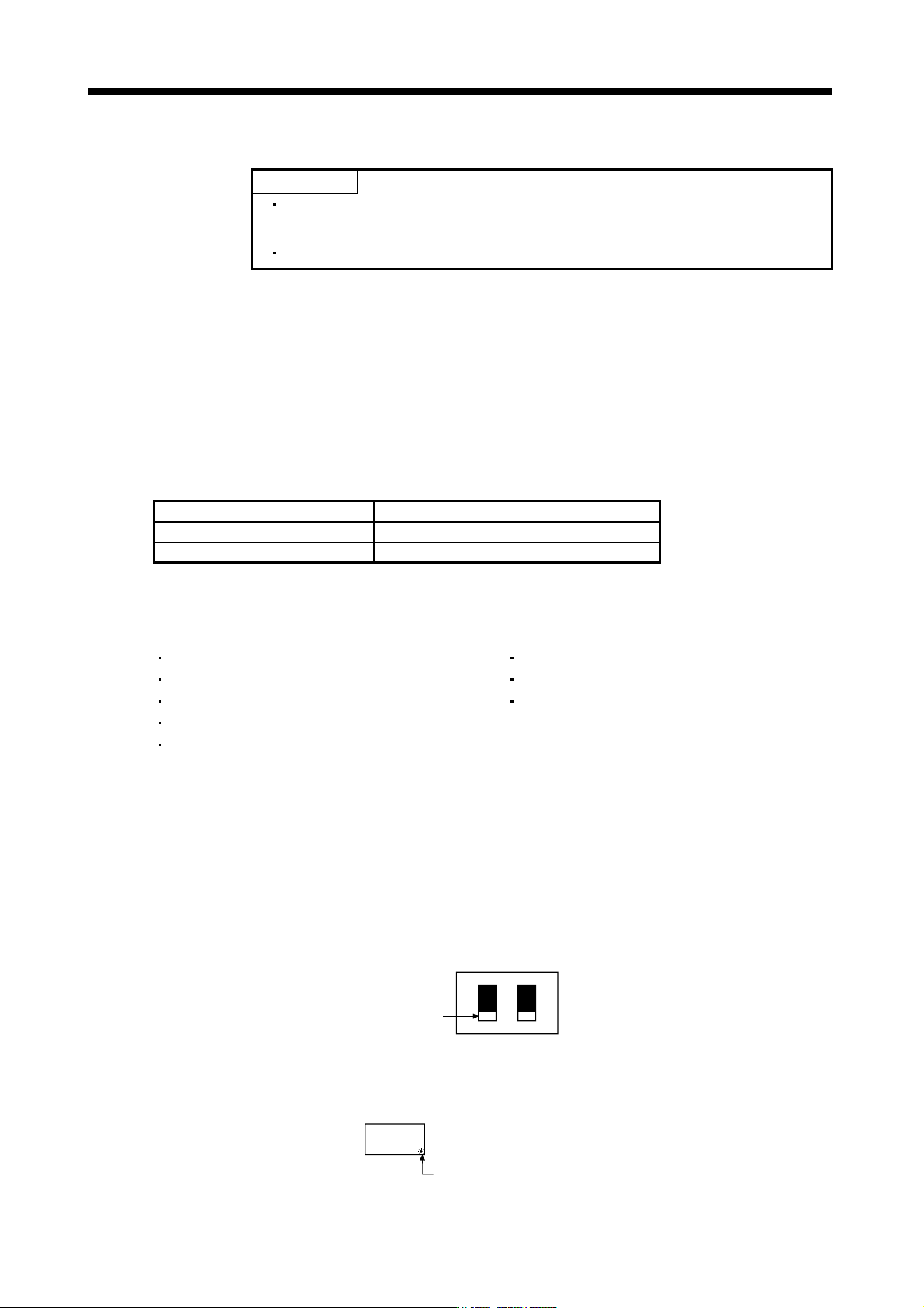
(2) Operating procedure
1) Switch off servo amplifier
2) Set parameter No.PC05 to "1", change test operation mode switch (SW2-1) to normal condition side
"Down", and then turn on the power supply.
SW2
DOWN
UP
12
Set SW2-1 to "DOWN"
3) Perform motor-less operation with the personal computer.
The display shows the following screen.
Decimal point flickers.
5 - 1
5. PARAMETERS
5. PARAMETERS
CAUTION
Never adjust or change the parameter values extremely as it will make operation
instable.
POINT
When the servo amplifier is connected with the servo system controller, the
parameters are set to the values of the servo system controller. Switching
power off, then on makes the values set on the MR Configurator (servo
configuration software) invalid and the servo system controller values valid.
Setting may not be made to some parameters and ranges depending on the
model or version of the servo system controller. For details, refer to the servo
system controller user's manual.
In this servo amplifier, the parameters are classified into the following groups on a function basis.
Parameter group Main description
Basic setting parameters
(No.PA
)
Make basic setting with these parameters. Generally, the operation is possible only with these
parameter settings.
Gain/filter parameters
(No.PB
)
Use these parameters when making gain adjustment manually.
Extension setting parameters
(No.PC
)
When changing settings such as analog monitor output signal or encoder electromagnetic brake
sequence output, use these parameters.
I/O setting parameters
(No.PD
)
Use these parameters when changing the I/O signals of the servo amplifier.
Mainly setting the basic setting parameters (No.PA
) allows the setting of the basic parameters at the time
of introduction.
5.1 Basic setting parameters (No.PA
)
POINT
Parameter whose symbol is preceded by * is made valid with the following
conditions.
* : Set the parameter value, switch power off once after setting, and then
switch it on again, or perform the controller reset.
**: Set the parameter value, switch power off once, and then switch it on
again.
Never change parameters for manufacturer setting.
5 - 2
5. PARAMETERS
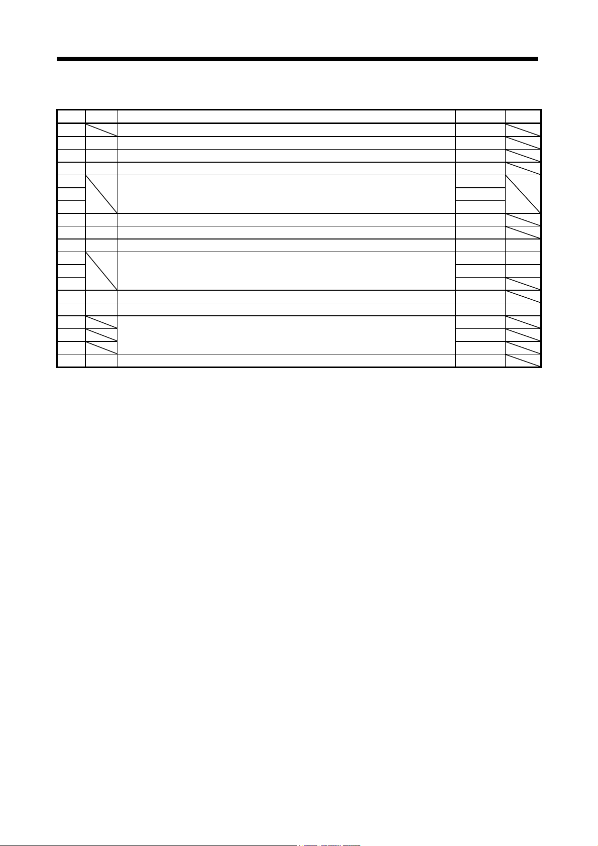
5.1.1 Parameter list
No. Symbol Name Initial value Unit
PA01 For manufacturer setting 0000h
PA02 **REG Regenerative option 0000h
PA03 *ABS Absolute position detection system 0000h
PA04 *AOP1 Function selection A-1 0000h
PA05
For manufacturer setting 0
PA06 1
PA07 1
PA08 ATU Auto tuning mode 0001h
PA09 RSP Auto tuning response 12
PA10 INP In-position range 100 pulse
PA11
For manufacturer setting 1000.0 %
PA12 1000.0 %
PA13 0000h
PA14 *POL Rotation direction selection 0
PA15 *ENR Encoder output pulses 4000 pulse/rev
PA16 For manufacturer setting 0
PA17 0000h
PA18 0000h
PA19 *BLK Parameter write inhibit 000Bh