sh030051g.pdf - 第410页
App. - 7 A PPENDI X App. 5.3 CNP1, CNP2, CNP3 wiring method (3.3.3 CNP1, CNP2, CNP3 wiring method) (a) Servo amplifier power supply connectors Servo amplif ier pow er supply con nectors CNP3 CNP1 CNP2 Connector for CNP1 …
App. - 6
A
PPENDI
X
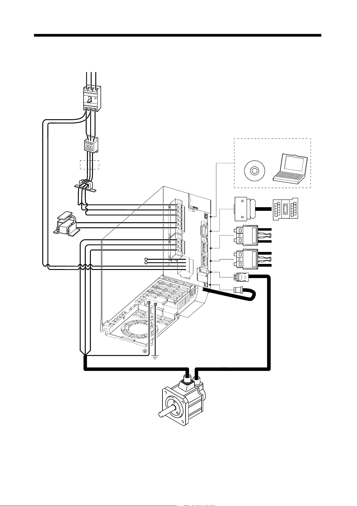
App. 5.2 Configuration including auxiliary equipment (1.8 Configuration including auxiliary equipment)
R S T
P
C
L
21
P
1
P
2
UV
W
L11
L
1
L
2
L3
CN5
CN3
CN2
CN1A
CN1B
CN4
Line noise filter
(FR-BLF)
(Note 3)
Power supply
Magnetic
contactor
(MC)
No-fuse breaker
(NFB) or fuse
Regenerative
option
(Note 2)
Power factor
improving DC
reactor
(FR-BEL)
(Note 2)
Servo amplifier
Junction
terminal
block
MR Configurator
Personal
computer
(Note 1)
Battery
MR-J3BAT
Servo system
controller or Front axis
servo amplifier CN1B
Rear servo amplifier
CN1A or Cap
Servo motor
Note 1. The battery (option) is used for the absolute position detection system in the position control mode.
2. The AC reactor can also be used. In this case, the DC reactor cannot be used. When not using DC reactor, short P
1-P2.
3. Refer to section 1.3 for the power supply specification.
App. - 7
A
PPENDI
X
App. 5.3 CNP1, CNP2, CNP3 wiring method (3.3.3 CNP1, CNP2, CNP3 wiring method)
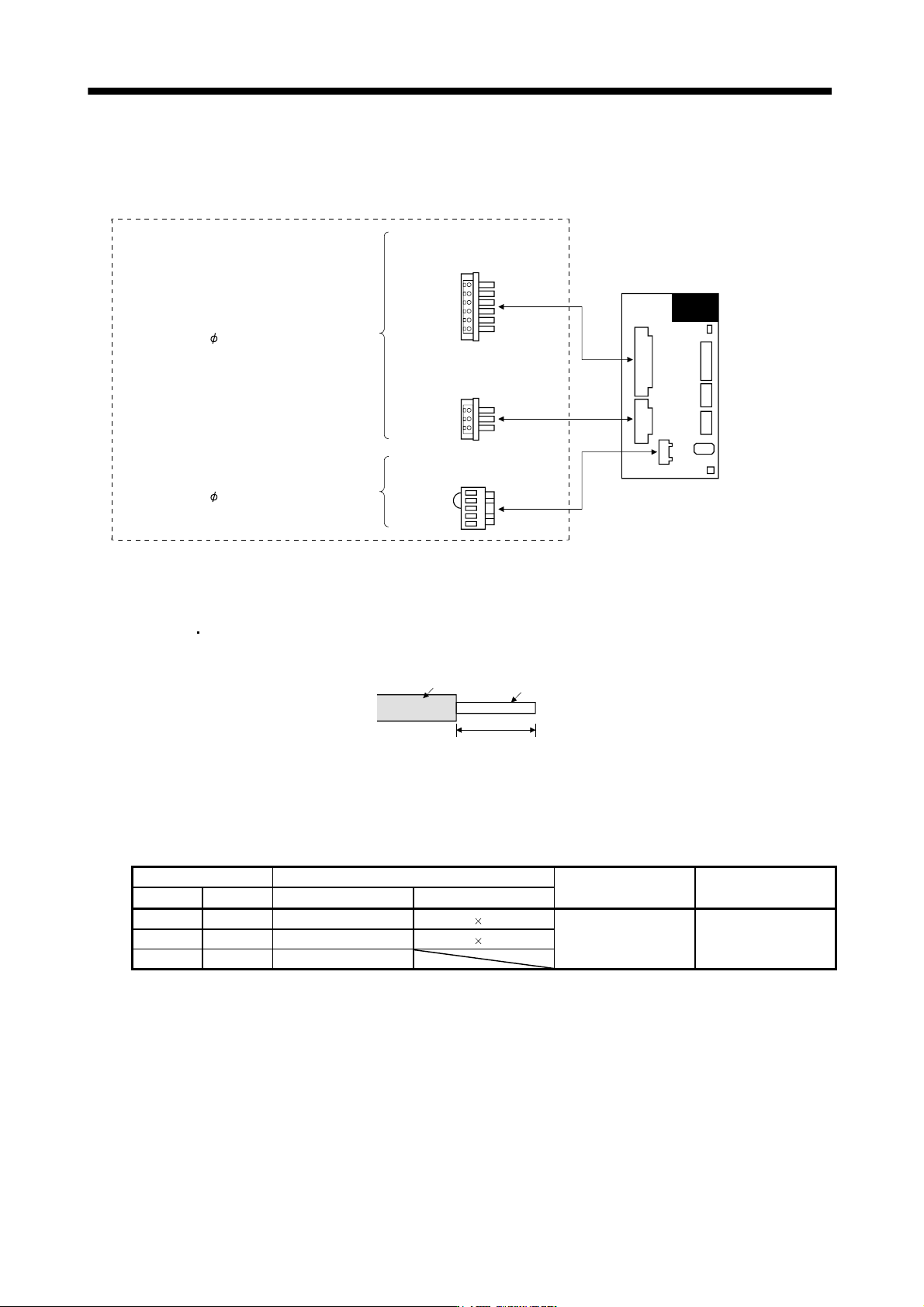
(a) Servo amplifier power supply connectors
Servo amplifier power supply connectors
CNP3
CNP1
CNP2
Connector for CNP1
PC4/6-STF-7.62-CRWH
(Phoenix Contact)
<Applicable cable example>
Cable finish OD: 5mm or less
Connector for CNP3
PC4/3-STF-7.62-CRWH
(Phoenix Contact)
Connector for CNP2(Note)
54928-0520 (Molex)
Servo amplifier
<Applicable cable example>
Cable finish OD: 3.8mm or less
Note. As twin type connector for CNP2 (L11, L21) is the same as MR-J3-100B or smaller. Refer to section (1) (c).
(b) Termination of the cables
1) CNP1
CNP3
Solid wire: After the sheath has been stripped, the cable can be used as it is.
7mm
Sheath
Core
Twisted wire: Use the cable after stripping the sheath and twisting the core. At this time, take care to
avoid a short caused by the loose wires of the core and the adjacent pole. Do not
solder the core as it may cause a contact fault. Alternatively, a bar terminal may be
used to put the wires together.
Cable size Bar terminal type
Crimping tool Manufacturer
[mm
2
] AWG For 1 cable For 2 cables
1.25/1.5 16 AI1.5-8BK AI-TWIN2 1.5-8BK
2.0/2.5 14 AI2.5-8BU AI-TWIN2 2.5-10BU CRIMPFOX-ZA3 Phoenix Contact
3.5 12 AI4-10Y
2) CNP2
CNP2 is the same as MR-J3-100B or smaller capacities. Refer to section 3.3.3 (1) (b).
App. - 8
A
PPENDI
X
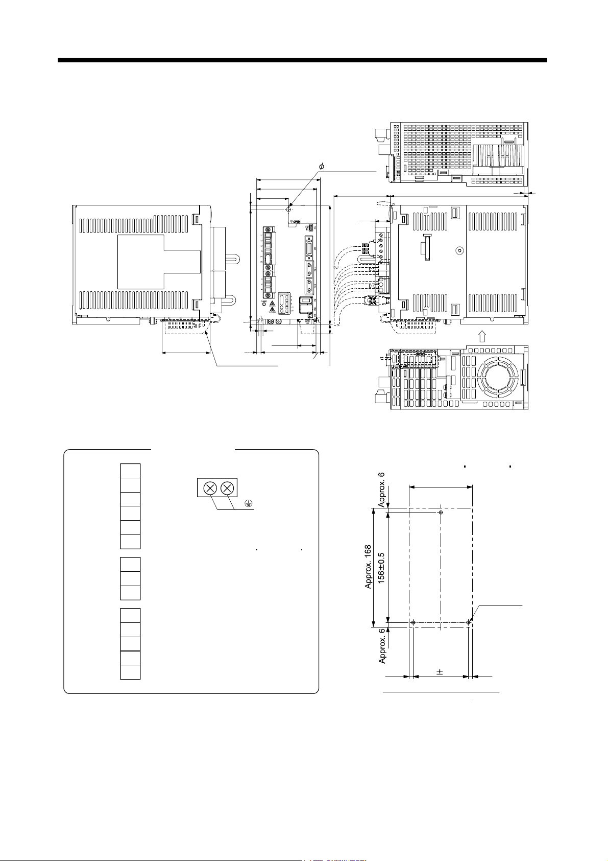
App. 5.4 OUTLINE DRAWINGS (Chapter 9 OUTLINE DRAWINGS)
[Unit: mm]
Approx.14
Approx.
25.5
90
168
6
78
6
45
6
156
6
6 mounting hole
195
21.4
Approx.80
Cooling fan
wind direction
Approx.68
6
85
With MR-J3BAT
6
Mass: 2.3 [kg] (5.07 [lb])
U
V
W
CNP3
P
C
D
L
11
L
21
CNP2
L1
L
2
L
3
N
P
1
P2
CNP1
Terminal signal layout
PE terminal
Screw size: M4
Tightening torque:
1.2 [N m] (10.6 [lb in])
Approx. 90
78 0.3
Approx. 6
Approx. 6
3-M5 screw
Mounting hole process drawing
Mounting screw
Screw size: M5
Tightening torque: 3.24 [N m] (28.7 [lb in])