sh030051g.pdf - 第77页
3 - 22 3. SIGNALS AND WI RING (4) How to insert the cable into Phoenix Contact connector POINT Do not use a precision driver be cause the cable cannot be tightene d with enough torque. Insertion of cables into Phoenix Co…
3 - 21
3. SIGNALS AND WIRING
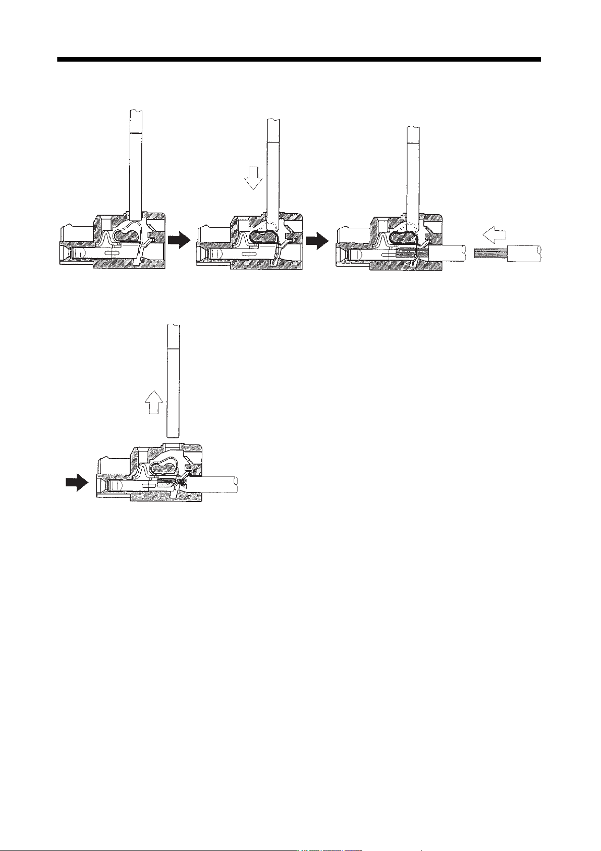
3) When using the flat-blade screwdriver - part 2
1) Insert the screwdriver into the
square window at top of the
connector.
2) Push the screwdriver in the
direction of arrow.
3) With the screwdriver pushed, insert the cable in the
direction of arrow. (Insert the cable as far as it will go.)
4) Releasing the screwdriver connects the cable.
3 - 22
3. SIGNALS AND WIRING
(4) How to insert the cable into Phoenix Contact connector
POINT
Do not use a precision driver because the cable cannot be tightened with
enough torque.
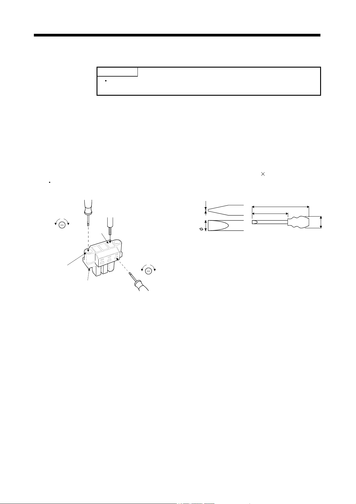
Insertion of cables into Phoenix Contact connector PC4/6-STF-7.62-CRWH or PC4/3-STF-7.62-CRWH is
shown as follows.
Before inserting the cable into the opening, make sure that the screw of the terminal is fully loose. Insert the
core of the cable into the opening and tighten the screw with a flat-blade screwdriver. When the cable is not
tightened enough to the connector, the cable or connector may generate heat because of the poor contact.
(When using a cable of 1.5mm2 or less, two cables may be inserted into one opening.)
Secure the connector to the servo amplifier by tightening the connector screw.
For securing the cable and the connector, use a flat-blade driver with 0.6mm blade edge thickness and
3.5mm diameter (Recommended flat-blade screwdriver: Phoenix Contact SZS 0.6
3.5). Apply 0.5 to 0.6
N
m torque to screw.
[Unit: mm]
Flat-blade
screwdriver
To loosen To tighten
Wire
Opening
To loosen To tighten
Flat-blade
screwdriver
Connector screw
Servo amplifier power
supply connector
3.5 0.6
180
100
(35)
Recommended flat-blade screwdriver dimensions
3 - 23
3. SIGNALS AND WIRING
3.4 Connectors and signal arrangements
POINT
The pin configurations of the connectors are as viewed from the cable
connector wiring section.
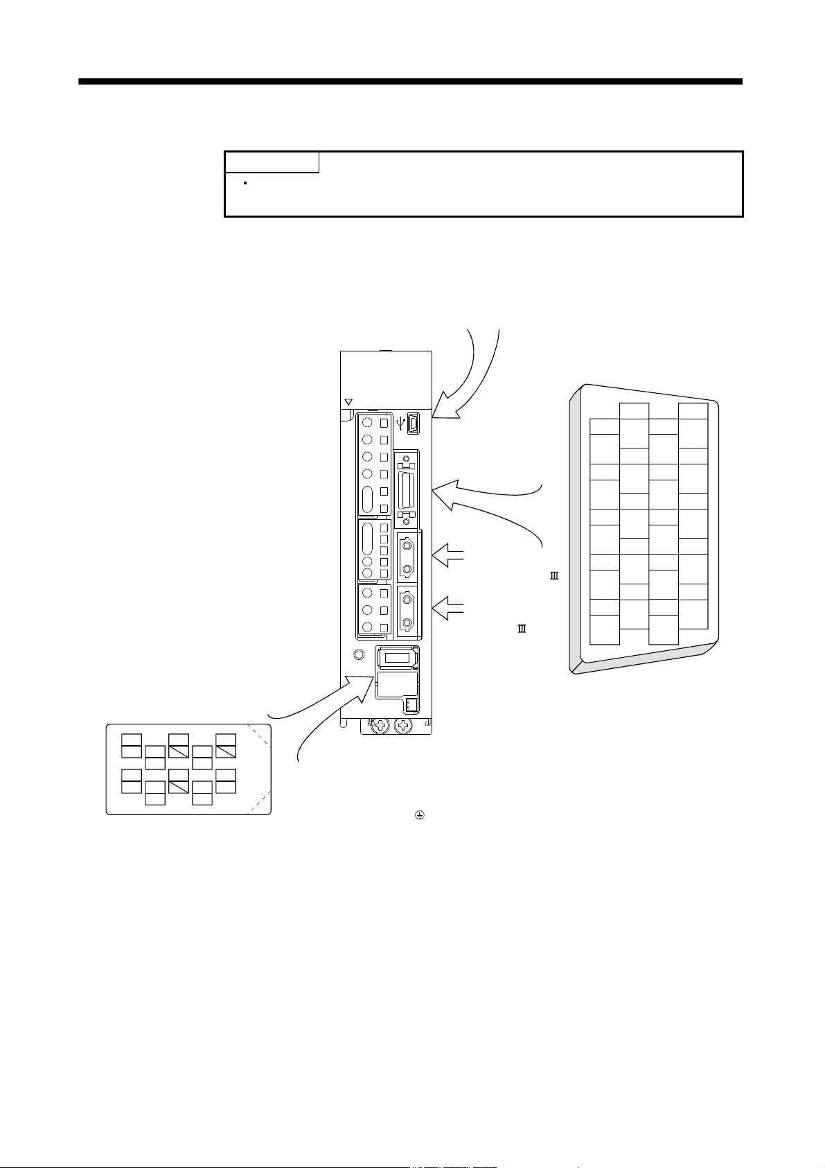
(1) Signal arrangement
The servo amplifier front view shown is that of the MR-J3-20B or less. Refer to chapter 9 Outline Drawings
for the appearances and connector layouts of the other servo amplifiers.
The 3M make connector is shown.
When using any other connector,
refer to section 11.1.2.
9
4
MRR
2
LG
8
6
1
P5
5
10
3
MR
7
BAT
CN2
MDR
MD
CN4 CN2L CN2 CN1B CN1A CN3 CN5
CHARGE
L
2
U
W
V
D
L
12
L11
C
P
N
P
1
P
2
L
3
L
1
OPEN
CN5 (USB connector)
Refer to section 11.8.
CN3
The frames of the CN2 and CN3
connectors are connected to the
PE (earth) terminal ( ) in the
amplifier.
Connector for
the front axis of
CN1A SSCNET
cable.
Connector for the
rear axis of CN1B
SSCNET cable.
2
111
12
4
313
14
6
515
16
8
717
18
10
919
20
DI1
LG LG
DI2
MO1
DOCOM
MBR
MO2
LA
DICOM
ALM
LAR
LZ
LB LBR
LZR
DICOM
INP DI1
EM1