sh030051g.pdf - 第68页
3 - 13 3. SIGNALS AND WI RING 3.3.2 Power-on sequence (1) Power-on procedure 1) Always wir e the power supply as sho wn in above se ction 3.1 using the magnetic con tactor with the main circuit power supply (three-phase:…
3 - 12
3. SIGNALS AND WIRING
3.3 Explanation of power supply system
3.3.1 Signal explanations
POINT
For the layout of connector and terminal block, refer to outline drawings in
chapter 9.
Abbreviation
Connection target
(Application)
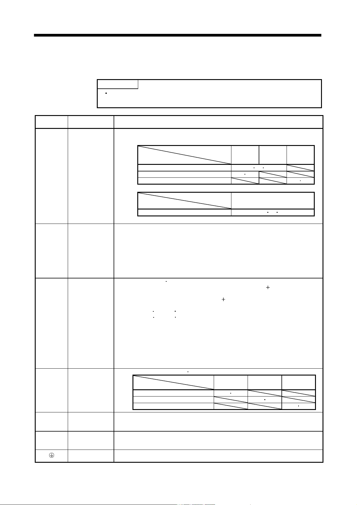
Description
L1
L
2
L
3
Main circuit power
supply
Supply the following power to L
1, L2, L3. For the 1-phase 200V to 230VAC power supply, connect
the power supply to L
1, L2, and keep L3 open.
Servo amplifier
Power supply
MR-J3-
10B to 70B
MR-J3-
100B to
22KB
MR-J3-
10B1 to
40B1
3-phase 200V to 230VAC, 50/60Hz L1 L2 L3
1-phase 200V to 230VAC, 50/60Hz L1 L2
1-phase 100V to 120VAC, 50/60Hz L1 L2
Servo amplifier
Power supply
MR-J3-60B4 to 22KB4
3-phase 380V to 480VAC, 50/60Hz L1 L2 L3
P1
P
2
Power factor
improving DC
reactor
1) MR-J3-700B or less
When not using the power factor improving DC reactor, connect P
1 and P2. (Factory-wired.)
When using the power factor improving DC reactor, disconnect P
1 and P2, and connect the
power factor improving DC reactor to P
1 and P2.
2) MR-J3-11KB(4) to 22KB(4)
MR-J3-11KB(4) to 22KB(4) do not have P
2.
When not using the power factor improving reactor, connect P
1 and P. (Factory-wired)
When using the power factor improving reactor, connect it to P and P
1.
Refer to section 11.13.
P
C
D
Regenerative
option
1) MR-J3-350B or less
MR-J3-200B4 or less
When using servo amplifier built-in regenerative resistor, connect P(
) and D. (Factory-
wired)
When using regenerative option, disconnect P(
) and D, and connect regenerative option to
P and C.
2) MR-J3-350B4
500B(4) 700B(4)
MR-J3-350B4
500B(4) 700B(4) do not have D.
When using servo amplifier built-in regenerative resistor, connect P and C. (Factory-wired)
When using regenerative option, disconnect P and C, and connect regenerative option to P
and C.
3) MR-J3-11KB(4) to 22KB(4)
MR-J3-11KB(4) to 22KB(4) do not have D.
When not using the power regenerative converter and the brake unit, make sure to connect
the regenerative option to P and C.
Refer to section 11.2 to 11.5.
L11
L
21
Control circuit
power supply
Supply the following power to L
11 L21.
Servo amplifier
Power supply
MR-J3-10B to
22KB
MR-J3-10B1 to
40B1
MR-J3-60B4 to
22KB4
1-phase 200V to 230VAC, 50/60Hz L11 L21
1-phase 100V to 120VAC, 50/60Hz L11 L21
1-phase 380V to 480VAC, 50/60Hz L11 L21
U
V
W
Servo motor power
Connect to the servo motor power supply terminals (U, V, W). During power-on, do not open or
close the motor power line. Otherwise, a malfunction or faulty may occur.
N
Return converter
Brake unit
When using the power regenerative converter/brake unit, connect it to P and N.
Do not connect to servo amplifier MR-J3-350B(4) or less.
For details, refer to section 11.3 to 11.5.
Protective earth
(PE)
Connect to the earth terminal of the servo motor and to the protective earth (PE) of the control
box to perform grounding.
3 - 13
3. SIGNALS AND WIRING
3.3.2 Power-on sequence
(1) Power-on procedure
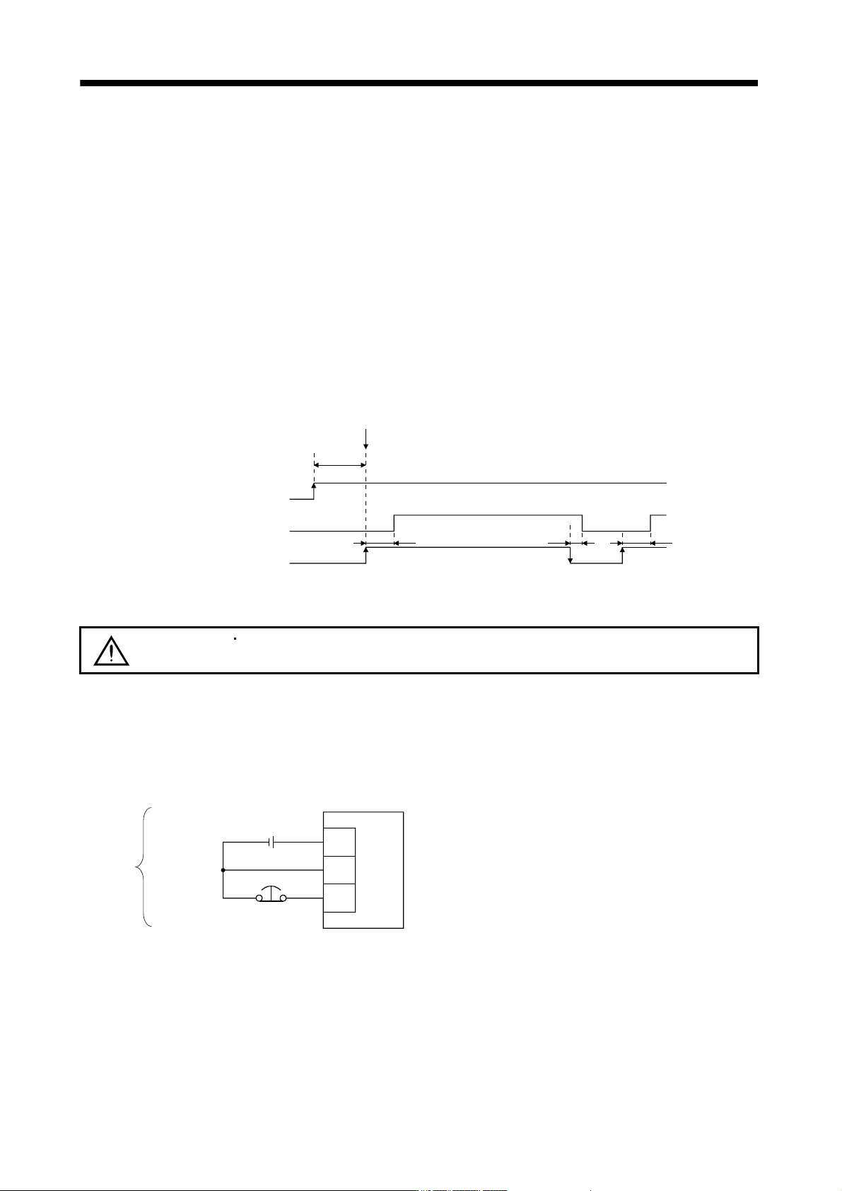
1) Always wire the power supply as shown in above section 3.1 using the magnetic contactor with the main
circuit power supply (three-phase: L
1
, L
2
, L
3
, single-phase: L
1
, L
2
). Configure up an external sequence
to switch off the magnetic contactor as soon as an alarm occurs.
2) Switch on the control circuit power supply L
11
, L
21
simultaneously with the main circuit power supply or
before switching on the main circuit power supply. If the main circuit power supply is not on, the display
shows the corresponding warning. However, by switching on the main circuit power supply, the warning
disappears and the servo amplifier will operate properly.
3) The servo amplifier can accept the servo-on command within 3s the main circuit power supply is
switched on. (Refer to paragraph (2) of this section.)
(2) Timing chart
(3s)
ON
OFF
ON
OFF
ON
OFF
10ms 95ms95ms
Base circuit
Servo-on command
(from controller)
SON accepted
Main circuit
Control circuit
power
(3) Forced stop
CAUTION
Install an forced stop circuit externally to ensure that operation can be stopped and
power shut off immediately.
If the controller does not have an forced stop function, make up a circuit that switches off main circuit power
as soon as EM1 is turned off at a forced stop. When EM1 is turned off, the dynamic brake is operated to
stop the servo motor. At this time, the display shows the servo forced stop warning (E6).
During ordinary operation, do not use forced stop (EM1) to alternate stop and run. The service life of the
servo amplifier may be shortened.
DICOM
DOCOM
EM1
24VDC
Servo amplifier
Forced stop
(Note)
Note. For the sink I/O interface. For the source I/O interface, refer to section 3.7.3.
3 - 14
3. SIGNALS AND WIRING
3.3.3 CNP1, CNP2, CNP3 wiring method
POINT
Refer to table 11.1 in section 11.11 for the wire sizes used for wiring.
MR-J3-500B or more MR-J3-350B4 or more does not have these connectors.
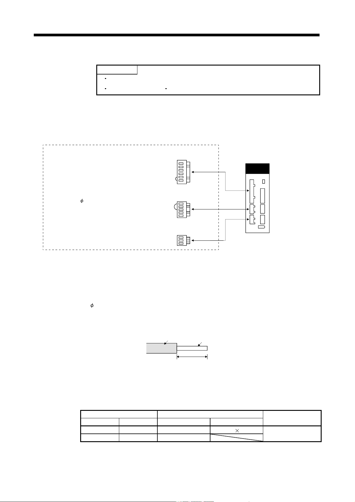
Use the supplied servo amplifier power supply connectors for wiring of CNP1, CNP2 and CNP3.
(1) MR-J3-10B to MR-J3-100B
(a) Servo amplifier power supply connectors
CNP2
CNP1
CNP3
Connector for CNP1
54928-0670 (Molex)
Connector for CNP2
54928-0520 (Molex)
Connector for CNP3
54928-0370 (Molex)
<Applicable cable example>
Cable finish OD: to 3.8mm
(Note)Servo amplifier power supply connectors
Servo amplifier
Note. These connectors are of insert type. As the crimping type, the following connectors (Molex) are recommended.
For CNP1: 51241-0600 (connector), 56125-0128 (terminal)
For CNP2: 51240-0500 (connector), 56125-0128 (terminal)
For CNP3: 51241-0300 (connector), 56125-0128 (terminal)
Crimping tool: CNP57349-5300
<Connector applicable cable example>
Cable finish OD: to
3.8mm
(b) Termination of the cables
Solid wire: After the sheath has been stripped, the cable can be used as it is.
8 to 9mm
Sheath
Core
Twisted wire: Use the cable after stripping the sheath and twisting the core. At this time, take care to
avoid a short caused by the loose wires of the core and the adjacent pole. Do not solder
the core as it may cause a contact fault. Alternatively, a bar terminal may be used to put
the wires together.
Cable size Bar terminal type
Crimping tool (Note 2)
[mm
2
] AWG For 1 cable (Note 1) For 2 cable
1.25/1.5 16 AI1.5-10BK AI-TWIN2 1.5-10BK
Variocrimp 4 206-204
2/2.5 14 AI2.5-10BU
Note 1. Manufacturer: Phoenix Contact
2. Manufacturer: WAGO