sh030051g.pdf - 第355页
13 - 54 13. SERVO AMPLIFIERS WI TH A LARGE CAPACITY ( 30k TO 55kW ) Functions at occurrence of an alarm (1) Any mode screen displays the current alarm. (2) The other screen is visible during occurrence of an a lar m. At …
13 - 53
13. SERVO AMPLIFIERS WITH A LARGE CAPACITY
(
30k TO 55kW
)
13.4.4 Alarm mode
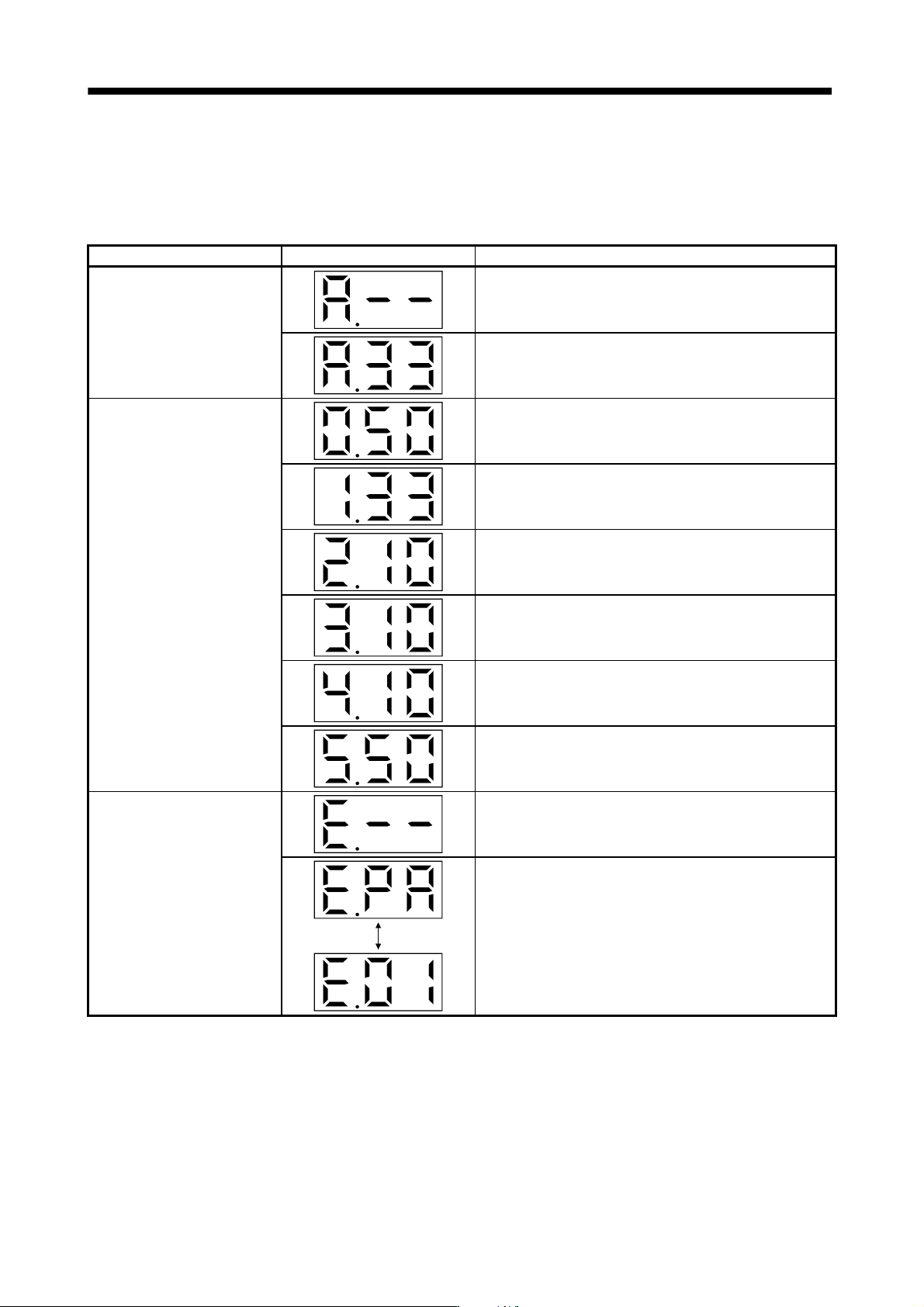
The current alarm, parameter error and point table error are displayed.
The lower 2 digits on the display indicate the alarm number that has occurred or the parameter number in error.
Display example are shown below.
Name Display Description
Current alarm
Indicates on occurrence of an alarm.
Indicates that overvoltage (A.33) occurred.
Flickers at alarm occurrence.
Indicates that the last alarm is overload (A.50).
Indicates that the second alarm in the past is overvoltage
(A.33).
Alarm history
Indicates that the third alarm in the past is undervoltage (A.10).
Indicates that the fourth alarm in the past is undervoltage
(A.10).
Indicates that the fifth alarm in the past is undervoltage (A.10).
Indicates that the sixth alarm in the past is overload (A.50).
Parameter error No.
Indicates no occurrence of parameter error (A.37).
Displayed
alternately
Indicates that the data of parameter No.PA01 is faulty.
13 - 54
13. SERVO AMPLIFIERS WITH A LARGE CAPACITY
(
30k TO 55kW
)
Functions at occurrence of an alarm
(1) Any mode screen displays the current alarm.
(2) The other screen is visible during occurrence of an alarm. At this time, the decimal point in the third digit
flickers.
(3) To clear any alarm, switch power off, then on or press the "SET" button on the current alarm screen. Note
that this should be done after removing the case of the alarm.
13.4.5 Parameter mode
POINT
The display section of the converter unit has three digits. When a parameter
No. is displayed, parameter group and parameter No. are displayed
alternately.
When, for example, "PA01" is displayed,
and are displayed
alternately.
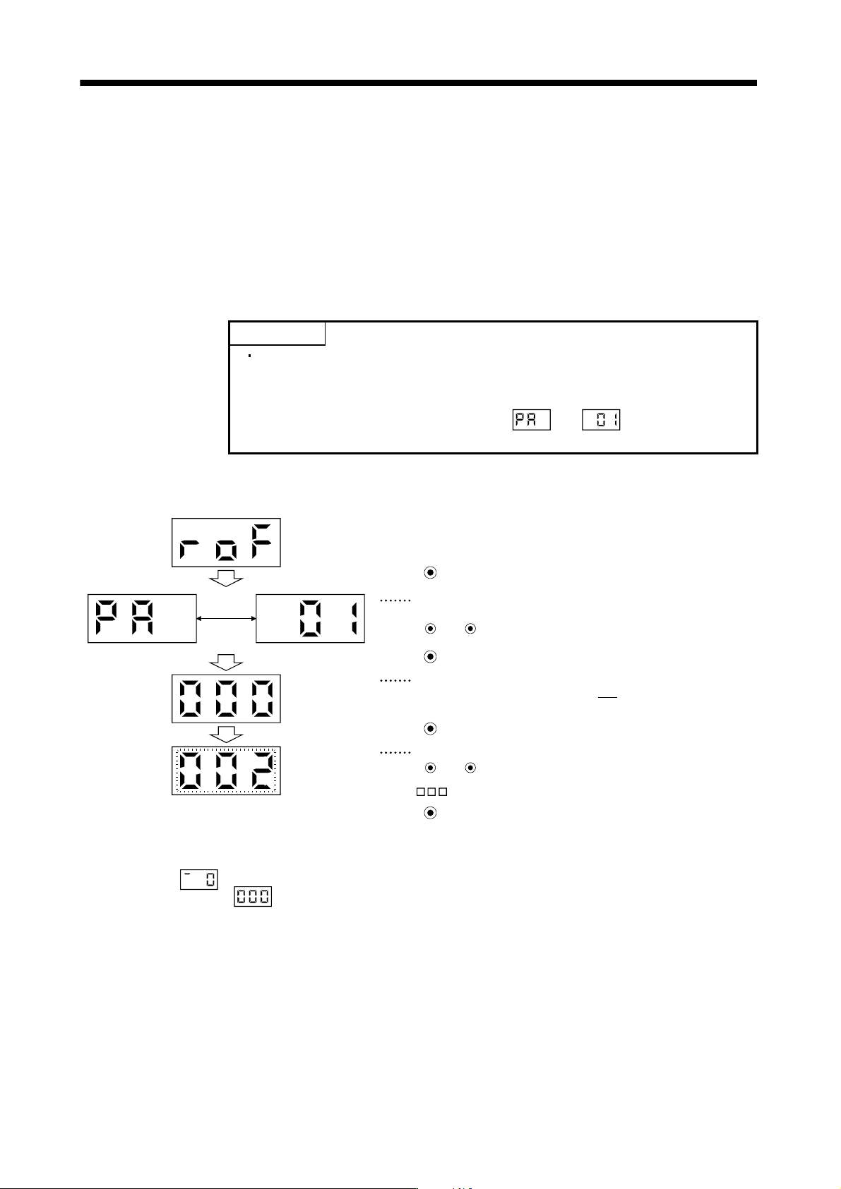
The following example gives the operation procedure after power-on for use of the regenerative options (MR-
RB137).
Displayed
alternately
( 2: MR-RB137 (3 pcs.) are used.)
(Note)
Press MODE three time
The parameter number is displayed.
For parameter No.PA01, “PA” and “01” are displayed alternately.
Press UP or DOWN to change the number.
Press MODE twice
The set value of the specified parameter number flickers.
In this case, the lower three digits “0
000” of the set value “0000” are
displayed.
Press MODE once
During flickering, the set value can be change.
Use UP or DOWN .
Press SET to enter.
Note. If the "MODE" button is pressed when the lower three digits of the four digits "0000" are displayed, the fourth digit "0000" is
displayed as
. However, do not change the setting of the fourth digit. Press the "MODE" button again to reset the display
to the lower three digits
.
To shift to the next parameter, press the "UP"/"DOWN" button.
When changing the parameter No.PA01 setting, change its set value, then switch power off once and switch it
on again to make the new value valid.
13 - 55
13. SERVO AMPLIFIERS WITH A LARGE CAPACITY
(
30k TO 55kW
)
13.5. Parameters for converter unit
CAUTION
Never adjust or change the parameter values extremely as it will make operation
instable.
POINT
Refer to chapter 5 for parameters for drive unit.
Parameter whose symbol is preceded by * is made valid with the following
conditions.
* : Set the parameter value, switch power off once after setting, and then
switch it on again, or perform the controller reset.
Never change parameters for manufacturer setting.
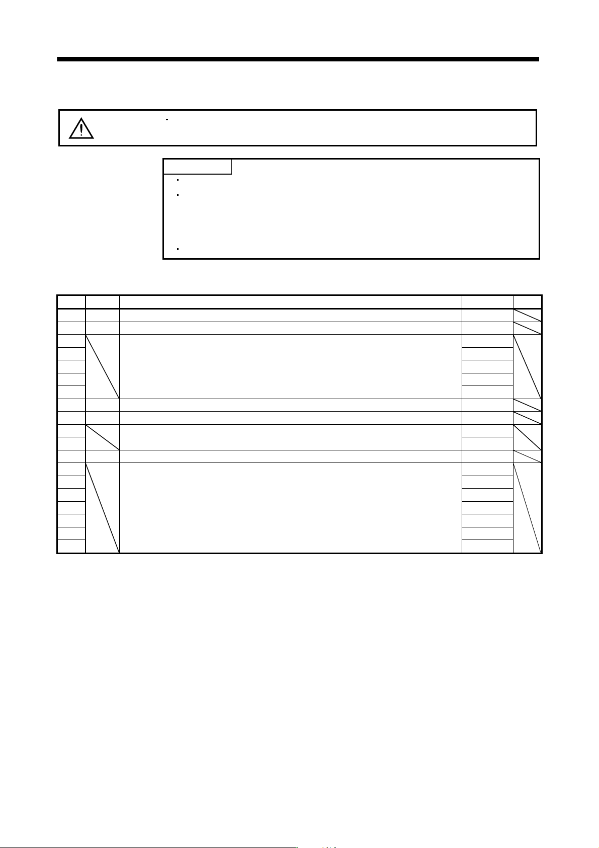
13.5.1 Parameter list
No. Symbol Name Initial value Unit
PA01 *REG Regenerative option 0000h
PA02 *MCC Magnetic contactor drive output selection 0001h
PA03
For manufacturer setting 0001h
PA04 0
PA05 100
PA06 0
PA07 100
PA08 *DMD Status display selection 0000h
PA09 *BPS Alarm history clear 0000h
PA10
For manufacturer setting 0
PA11 0000h
PA12 *DIF Input filter setting 0002h
PA13
For manufacturer setting 0000h
PA14 0000h
PA15 0000h
PA16 0000h
PA17 0000h
PA18 0000h
PA19 0000h