sh030051g.pdf - 第45页
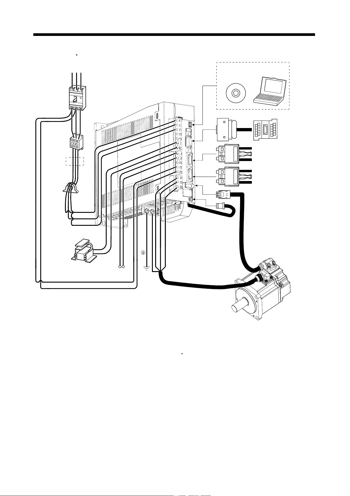
1 - 24 1. FUNCTIONS AND CONFIGURATIO N (3) MR-J3-200B(4) R S T L 21 L 11 C P (Note 3) Power supply No-fuse breaker (NFB) or fuse Magne tic contactor (MC) (Note 2) Line noise filter (FR-BSF0 1) (Note 2) Power factor impro…
1 - 23
1. FUNCTIONS AND CONFIGURATION
(2) MR-J3-60B4
MR-J3-100B4
(Note 3)
Power supply
R S T
No-fuse breaker
(NFB) or fuse
Magnetic
contactor
(MC)
(Note 2)
Line noise
filter
(FR-BSF01)
L
2
L
3
(Note 2)
Power factor
improving DC
reactor
(FR-BEL-H)
P
1
P
2
Regenerative option
PC
L
11
L21
UVW
(Note 1)
Battery
MR-J3BAT
CN5
CN3
CN1A
CN1B
CN2
CN4
MR Configurator
Personal
computer
Junction
terminal
block
Servo system
controller or Front axis
servo amplifier CN1B
Rear servo amplifier
CN1A or Cap
Servo motor
Servo amplifier
L
1
Note 1. The battery (option) is used for the absolute position detection system in the position control mode.
2. The AC reactor can also be used. In this case, the DC reactor cannot be used. When not using DC reactor, short P
1 and P2.
3. A 1-phase 200V to 230VAC power supply may be used with the servo amplifier of MR-J3-70B or less.
For 1-phase 200V to 230VAC, connect the power supply to L
1 L2 and leave L3 open. Refer to section 1.3 for the power supply
specification.
1 - 24
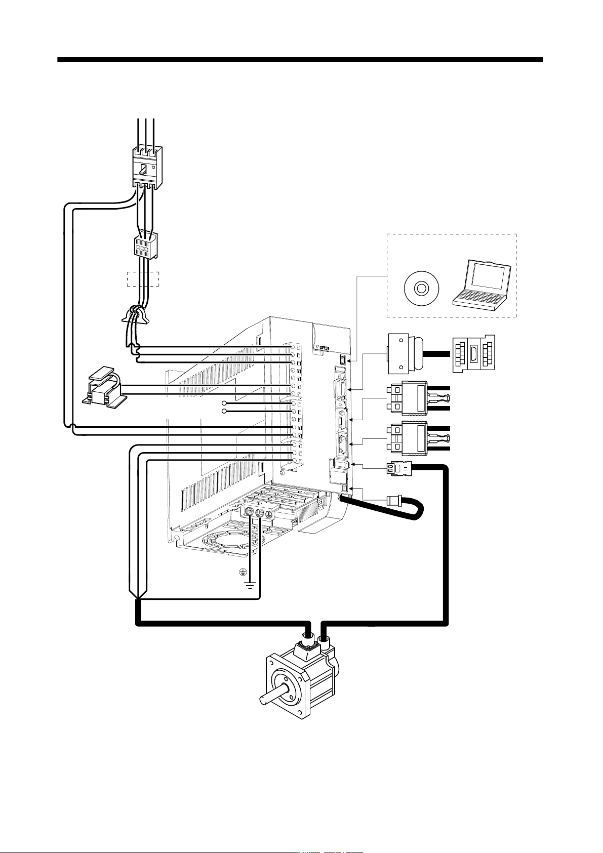
1. FUNCTIONS AND CONFIGURATION
(3) MR-J3-200B(4)
R S T
L21
L11
C
P
(Note 3)
Power supply
No-fuse breaker
(NFB) or fuse
Magnetic
contactor
(MC)
(Note 2)
Line noise filter
(FR-BSF01)
(Note 2)
Power factor
improving DC
reactor
(FR-BEL/
FR-BEL-H)
L
1
L2
L
3
P
1
Regenerative
option
Servo amplifier
CN5
CN3
CN1A
CN1B
CN2
CN4
(Note 1)
Battery
MR-J3BAT
Junction
terminal
block
Servo system
controller or Front axis
servo amplifier CN1B
Rear servo amplifier
CN1A or Cap
MR Configurator
Servo motor
UV W
Personal
computer
P
2
(Note 4)
Note 1. The battery (option) is used for the absolute position detection system in the position control mode.
2. The AC reactor can also be used. In this case, the DC reactor cannot be used. When not using DC reactor, short P
1 and P2.
3. Refer to section 1.3 for the power supply specification.
4. Connectors (CNP1, CNP2, and CNP3) and appearance of MR-J3-200B servo amplifier have been changed from January 2008
production. Model name of the existing servo amplifier is changed to MR-J3-200B-RT. For MR-J3-200B-RT, refer to appendix 5.
1 - 25
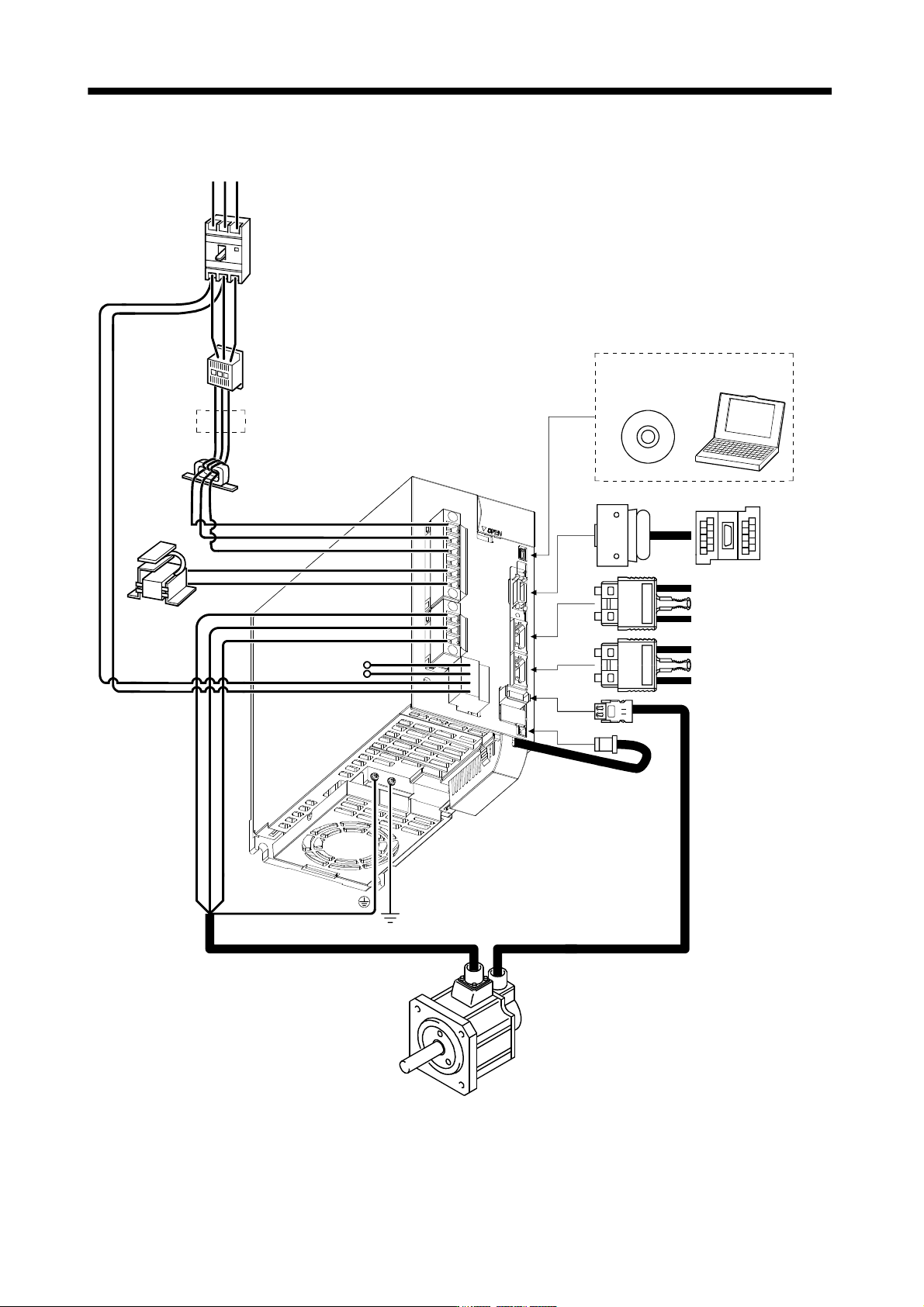
1. FUNCTIONS AND CONFIGURATION
(4) MR-J3-350B
R S T
P
C
L
21
P
1
P2
UV
W
L
11
L1
L
2
L3
CN5
CN3
CN2
CN1A
CN1B
CN4
Line noise filter
(FR-BLF)
(Note 3)
Power supply
Magnetic
contactor
(MC)
No-fuse breaker
(NFB) or fuse
Regenerative
option
(Note 2)
Power factor
improving DC
reactor
(FR-BEL)
(Note 2)
Servo amplifier
Junction
terminal
block
MR Configurator
Personal
computer
(Note 1)
Battery
MR-J3BAT
Servo system
controller or Front axis
servo amplifier CN1B
Rear servo amplifier
CN1A or Cap
Servo motor
Note 1. The battery (option) is used for the absolute position detection system in the position control mode.
2. The AC reactor can also be used. In this case, the DC reactor cannot be used. When not using DC reactor, short P
1 and P2.
3. Refer to section 1.3 for the power supply specification.