sh030051g.pdf - 第224页
11 - 19 11. OPTIONS AND AUXILI ARY EQUIPMENT 11.1.5 SSCNET cable POINT Do not see directly the light generated from CN1A CN1B con nector of servo amplifier or the end of SSCNET cable. When the light gets into eye, you ma…
11 - 18
11. OPTIONS AND AUXILIARY EQUIPMENT
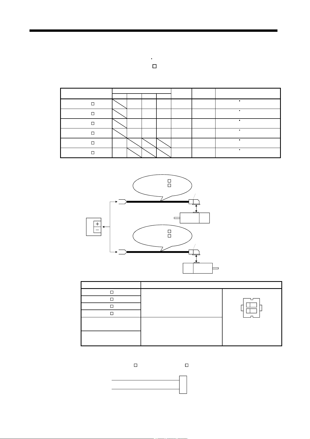
11.1.4 Motor brake cables
These cables are motor brake cables for the HF-MP
HF-KP series servo motors. The numerals in the Cable
length field of the table are the symbols entered in the
part of the cable model. The cables of the lengths with
the symbols are available.
Refer to section 3.11 when wiring.
Cable model
Cable length
Protective
structure
Flex life Application
0.3m 2m 5m 10m
MR-PWS1CBL M-A1-L 2 5 10 IP65 Standard
For HF-MP
HF-KP servo motor
Load side lead
MR-PWS1CBL M-A2-L 2 5 10 IP65 Standard
For HF-MP
HF-KP servo motor
Opposite-to-load side lead
MR-PWS1CBL M-A1-H 2 5 10 IP65
Long flex
life
For HF-MP
HF-KP servo motor
Load side lead
MR-PWS1CBL M-A2-H 2 5 10 IP65
Long flex
life
For HF-MP
HF-KP servo motor
Opposite-to-load side lead
MR-PWS2CBL M-A1-L 03 IP55 Standard
For HF-MP
HF-KP servo motor
Load side lead
MR-PWS2CBL M-A2-L 03 IP55 Standard
For HF-MP
HF-KP servo motor
Opposite-to-load side lead
(1) Connection of servo amplifier and servo motor
1)
Servo motor
HF-MP
HF-KP
24VDC power
supply for
electromagnetic
brake
MR-BKS1CBL M-A2-L
MR-BKS1CBL M-A2-H
MR-BKS2CBL03M-A2-L
1)
Servo motor
HF-MP
HF-KP
MR-BKS1CBL M-A1-L
MR-BKS1CBL M-A1-H
MR-BKS2CBL03M-A1-L
or
Cable model
1) For motor brake connector
MR-BKS1CBL M-A1-L
Connector: JN4FT02SJ1-R
Hood, socket insulator
Bushing, ground nut
Contact: ST-TMH-S-C1B-100-(A534G)
Crimping tool: CT160-3-TMH5B
(Japan Aviation Electronics Industry)
B1
B2
1
2
View seen from wiring side.
Signal layout
MR-BKS1CBL M-A2-L
MR-BKS1CBL M-A1-H
MR-BKS1CBL M-A2-H
MR-BKS2CBL03M-A1-L
Connector: JN4FT02SJ2-R
Hood, socket insulator
Bushing, ground nut
Contact: ST-TMH-S-C1B-100-(A534G)
Crimping tool: CT160-3-TMH5B
(Japan Aviation Electronics Industry)
MR-BKS2CBL03M-A2-L
(2) Internal wiring diagram
AWG 20
AWG 20
B1
B2
MR-BKS1CBL M-A1-H MR-BKS1CBL M-A2-H
MR-BKS2CBL03M-A1-L MR-BKS2CBL03M-A2-L
(Note)
Note. These are not shielded cables.
11 - 19
11. OPTIONS AND AUXILIARY EQUIPMENT
11.1.5 SSCNET
cable
POINT
Do not see directly the light generated from CN1A CN1B connector of servo
amplifier or the end of SSCNET
cable. When the light gets into eye, you
may feel something is wrong for eye. (The light source of SSCNET
complies
with class1 defined in JIS C6802 or IEC60825-1.)
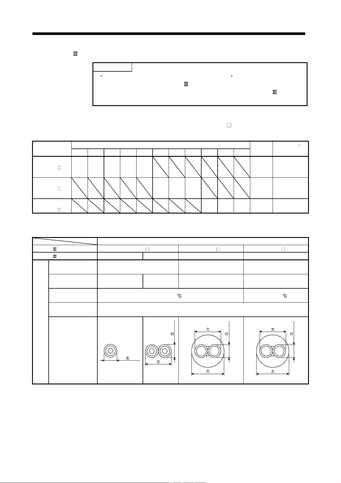
(1) Model explanations
Numeral in the column of cable length on the table is a symbol put in the
part of cable model. Cables of
which symbol exists are available.
Cable model
Cable length
Flex life
Application
remark
0.15m 0.3m 0.5m 1m 3m 5m 10m 20m 30m 40m 50m
MR-J3BUS M 015 03 05 1 3 Standard
Using inside
panel standard
cord
MR-J3BUS M-A 5 10 20 Standard
Using outside
panel standard
cable
(Note)
MR-J3BUS
M-B
30 40 50
Long flex
life
Using long
distance cable
Note. For cable of 30m or less, contact our company.
(2) Specifications
Description
SSCNET cable model MR-J3BUS M MR-J3BUS M-A MR-J3BUS M-B
SSCNET cable length 0.15m 0.3 to 3m 5 to 20m 30 to 50m
Optical
cable
(cord)
Minimum bend radius 25mm
Enforced covering cord: 50mm
Cord: 25mm
Enforced covering cord: 50mm
Cord: 30mm
Tension strength 70N 140N
420N
(Enforced covering cord)
980N
(Enforced covering cord)
Temperature range
for use (Note)
-40 to 85
-20 to 70
Ambient
Indoors (no direct sunlight)
No solvent or oil
External appearance
[mm]
2.2 0.07
4.4 0.1
2.2 0.07
6.0 0.2
2.2 0.07
4.4 0.1
4.4 0.4
7.6 0.5
2.2 0.2
Note. This temperature range for use is the value for optical cable (cord) only. Temperature condition for the connector is the same as
that for servo amplifier.
11 - 20
11. OPTIONS AND AUXILIARY EQUIPMENT
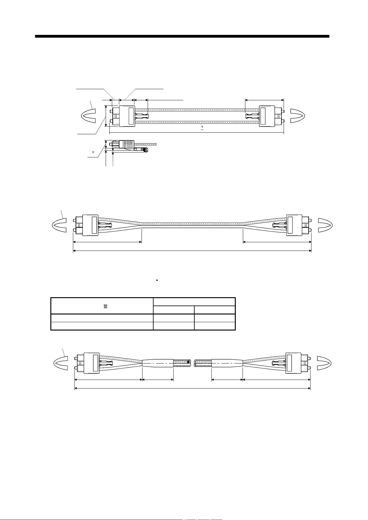
(3) Outline drawings
(a) MR-J3BUS015M
[Unit: mm]
(13.4)
(2.3)
(1.7)
(37.65)
(15)
(6.7)
(20.9)
Protective tube
0
150
50
0
8
(b) MR-J3BUS03M to MR-J3BUS3M
Refer to the table shown in (1) of this section for cable length (L).
[Unit: mm]
(100) (100)
L
(Note)
Protective tube
Note. Dimension of connector part is the same as that of MR-J3BUS015M.
(c) MR-J3BUS5M-A to MR-J3BUS20M-A
MR-J3BUS30M-B to MR-J3BUS50M-B
Refer to the table shown in (1) of this section for cable length (L).
SSCNET cable
Distortion dimension [mm]
A B
MR-J3BUS5M-A to MR-J3BUS20M-A 100 30
MR-J3BUS30M-B to MR-J3BUS50M-B 150 50
[Unit: mm]
(A) (A)
L
(Note)
Protective tube
(B)(B)
Note. Dimension of connector part is the same as that of MR-J3BUS015M.