sh030051g.pdf - 第360页
13 - 59 13. SERVO AMPLIFIERS WI TH A LARGE CAPACITY ( 30k TO 55kW ) Display Name Definition Cause Action A.30 Regenerative error Permissible regenerative power of regenerative option is exceeded. 1. Wrong setting of para…
13 - 58
13. SERVO AMPLIFIERS WITH A LARGE CAPACITY
(
30k TO 55kW
)
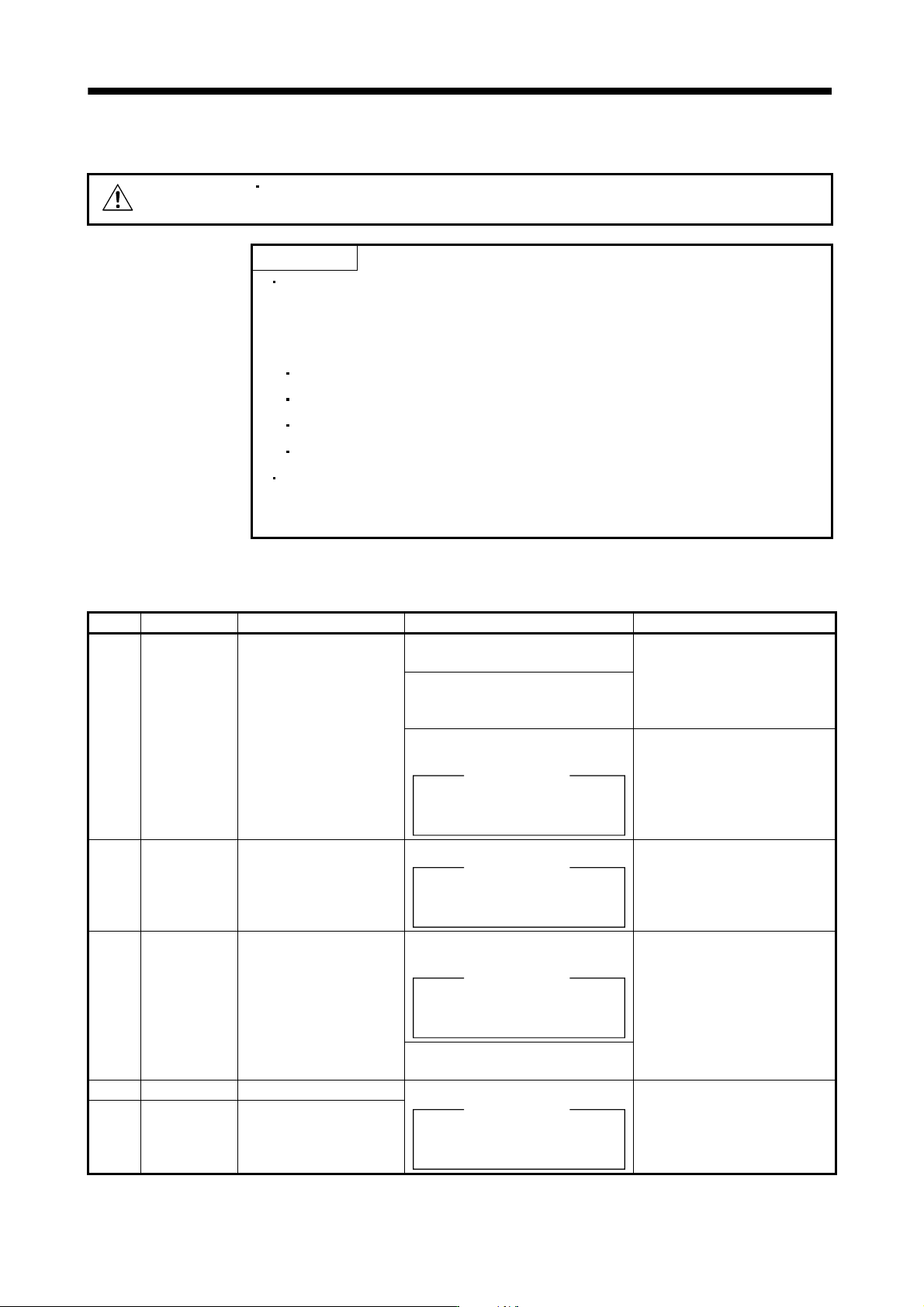
(2) Remedies for alarms
CAUTION
When any alarm has occurred, eliminate its cause, ensure safety, then reset the
alarm, and restart operation. Otherwise, injury may occur.
POINT
When any of the following alarms has occurred, always remove its cause and
allow about 30 minutes for cooling before resuming operation. If operation is
resumed by switching control circuit power off, then on to reset the alarm, the
converter unit and regenerative option may become faulty.
Regenerative error (A.30)
Over load 1 (A.50)
Over load 2 (A.51)
Main circuit device overheat (A.45)
The alarm can be deactivated by switching the power off, then on or by the
error reset command from the host controller. Refer to (1) in this section for
details.
When an alarm occurs, the trouble (ALM) signal switches off and the display section shows the alarm number.
Remove the cause of the alarm in accordance with this section.
Display Name Definition Cause Action
A.10 Undervoltage Power supply voltage
dropped.
1. Instantaneous control power failure
occurred for more than 60ms.
Review the power supply.
2. Shortage of power supply capacity
caused the power supply voltage to
drop at start, etc.
3. Failure of the part in the converter
unit.
Checking method
Alarm (A.10) occurs if power is
switched on after connectors
disconnected.
Change the Converter unit.
A.12 Memory error 1
(RAM)
RAM memory fault Failure of the part in the converter unit.
Checking method
Alarm (A.12) occurs if power is
switched on after connectors
disconnected.
Change the converter unit.
A.15 Memory error 2
(EEP-ROM)
EEP-ROM fault 1. Failure of the part in the converter
unit.
Checking method
Alarm (A.15) occurs if power is
switched on after connectors
disconnected.
Change the converter unit.
2. The number of write times to EEP-
ROM exceeded 100,000.
A.17 Board error CPU/parts fault Failure of the part in the converter unit. Change the converter unit.
A.19 Memory error 3
(Flash-ROM)
ROM memory fault
Checking method
Alarm (A.17/A.19) occurs if power is
switched on after connectors
disconnected.
13 - 59
13. SERVO AMPLIFIERS WITH A LARGE CAPACITY
(
30k TO 55kW
)
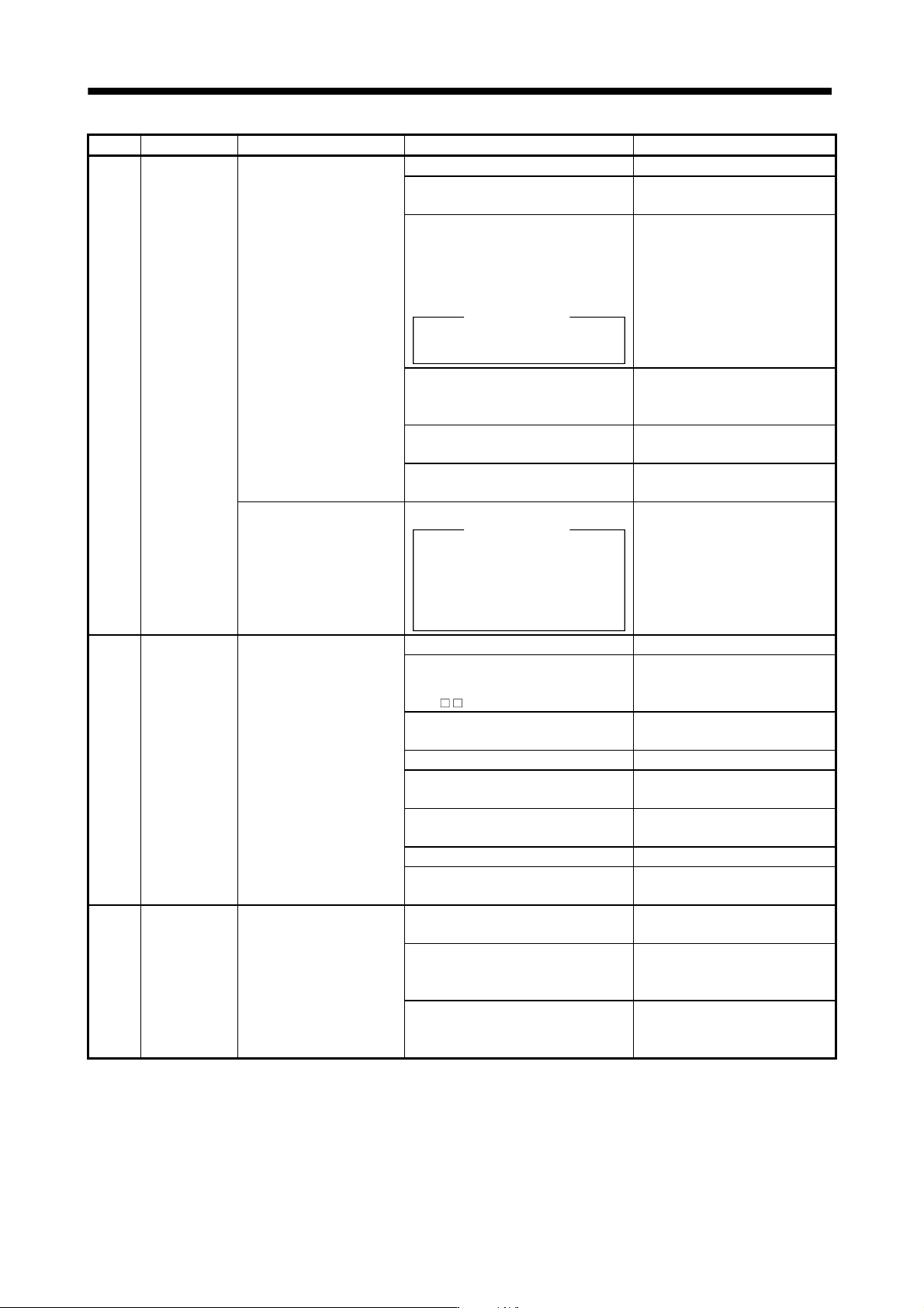
Display Name Definition Cause Action
A.30 Regenerative
error
Permissible regenerative
power of regenerative
option is exceeded.
1. Wrong setting of parameter No.PA01 Set correctly.
2. Regenerative option is not
connected.
Connect correctly.
3. High-duty operation or continuous
regenerative operation caused the
permissible regenerative power of
the regenerative option to be
exceeded.
Checking method
Call the status display and check the
regenerative load ratio.
1. Reduce the frequency of
positioning.
2. Use the regenerative option of
larger capacity.
3. Reduce the load.
4. Power supply voltage is abnormal.
MR-J3-CR55K: 260VAC or more
MR-J3-CR55K4: 520VAC or more
Review power supply
5. Regenerative option faulty. Change converter unit or
regenerative option.
6. Ground fault occurred in servo motor
power (U, V, W).
Correct the wiring.
Regenerative transistor fault 7. Regenerative transistor faulty.
Checking method
1)
2)
The regenerative option has
overheated abnormally.
The alarm occurs even after
removal of the built-in
regenerative resistor or
regenerative option.
Change the converter unit.
A.33 Over voltage Converter bus voltage
exceeded to following
voltage.
MR-J3-CR55K: 400VDC
MR-J3-CR55K4: 800VDC
1. Regenerative option is not used. Use the regenerative option.
2. Though the regenerative option is
used, the parameter No.PA01 setting
is "
00 (not used)".
Set correctly.
3. Lead of regenerative option is open
or disconnected.
1. Change lead.
2. Connect correctly.
4. Regenerative transistor faulty. Change the converter unit.
5. Wire breakage of regenerative
option.
Change the regenerative option.
6. Capacity of regenerative option is
insufficient.
Add regenerative option or
increase capacity.
7. Power supply voltage high. Review the power supply.
8. Ground fault occurred in servo motor
power (U, V, W).
Correct the wiring.
A.37 Parameter
error
Parameter setting is wrong. 1. Converter unit fault caused the
parameter setting to be rewritten.
Change the converter unit.
2. Regenerative option not used with
converter unit was selected in
parameter No.PA02.
Set parameter No.PA01 correctly.
3. The number of write times to
EEP-ROM exceeded 100,000 due to
parameter write, etc.
Change the converter unit.
13 - 60
13. SERVO AMPLIFIERS WITH A LARGE CAPACITY
(
30k TO 55kW
)
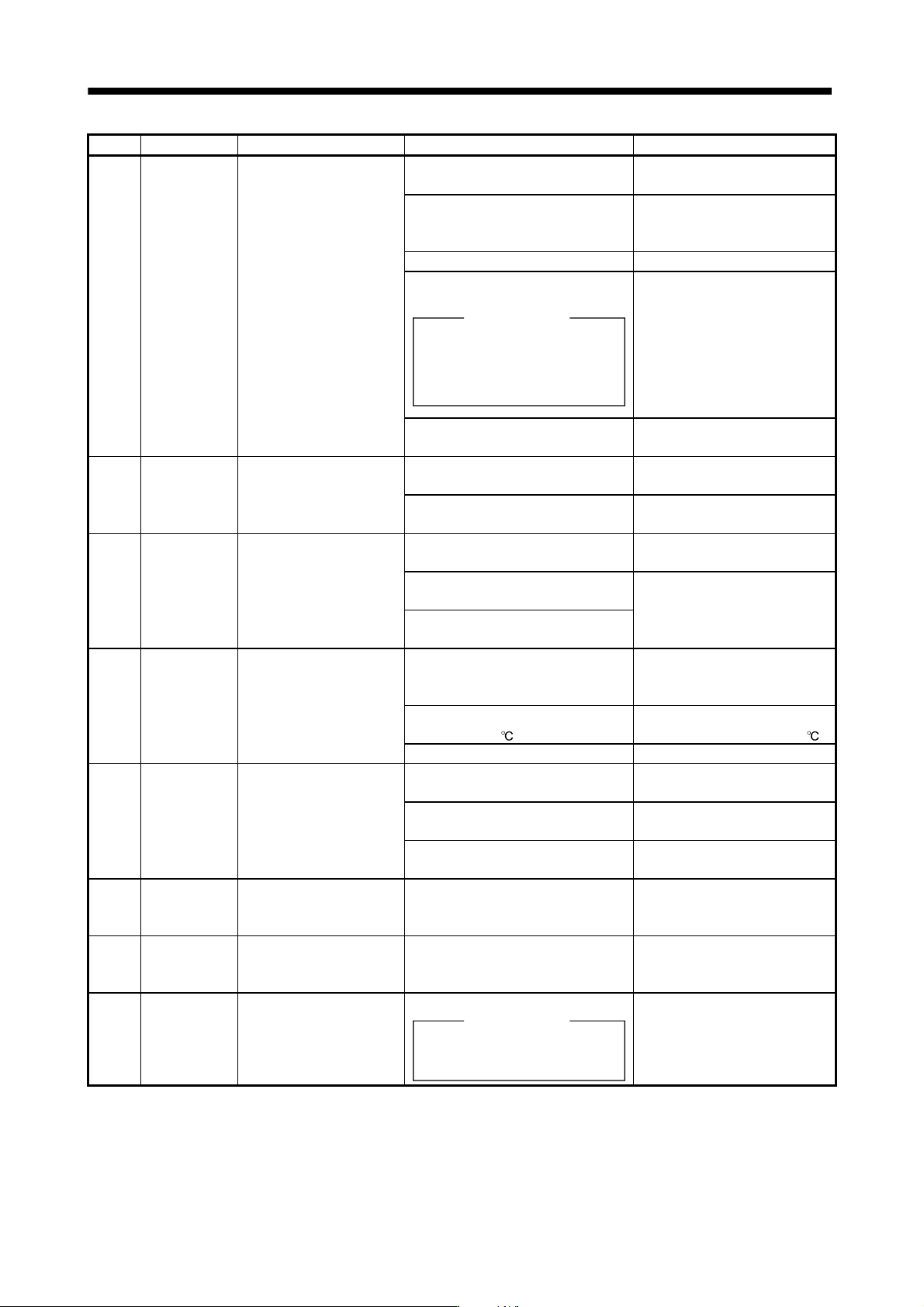
Display Name Definition Cause Action
A.38 MC drive circuit
error
Magnetic contactor drive
circuit error
(When the magnetic
contactor is turned on: the
main circuit power supply is
not turned on within two
seconds after the servo-on
of the drive unit.
When the magnetic
contactor is opened: the
main circuit power supply is
turned on although the
magnetic contactor is
opened.)
1. Wrong connection of the magnetic
contactor.
Review the wiring.
2. Parameters specifying whether to
use/not use the magnetic contactor
do not match the configuration.
Set parameter No.PA02 correctly.
3. Magnetic contactor failed. Change the magnetic contactor.
4. Magnetic contactor drive circuit
faulty.
Checking method
Check the output of magnetic
contactor control connector (CNP1) .
Power supply voltage is applied to
this connector. Take care to avoid an
electric shock at connecting.
Change the converter unit.
5. Mismatch of an external sequence. Review the power-on sequence.
(Refer to section 3.3.2.)
A.39 Open phase Power supply error 1. Any of L
1
, L
2
and L
3
is disconnected.
Or, open.
Review the wiring.
2. Failure of the part in the converter
unit.
Change the converter unit.
A.3A Inrush current
suppressor
circuit error
Inrush current suppressor
circuit error
1. Power-on/off was repeated with high
frequency.
Review operation pattern.
2. Inrush current suppressor resistance
overheated.
Change the converter unit.
3. Inrush current suppressor circuit
faulty.
A.45 Main circuit
device
overheat
Main circuit device
overheat.
1. The power supply was turned on and
off continuously by overloaded
status.
Review operation pattern.
2. Ambient temperature of converter
unit is over 55
.
Review environment so that
ambient temperature is 0 to 55 .
3. Converter unit faulty. Change the converter unit.
A.47 Cooling fan
alarm
The cooling fan of the
converter unit stopped, or its
speed decreased to or
below the alarm level.
1. Cooling fan life expiration. (Refer to
section 2.6.)
Change the cooling fan of the
converter unit.
2. Foreign matter caught in the cooling
fan stopped rotation.
Remove the foreign matter.
3. The power supply of the cooling fan
failed.
Change the converter unit.
A.50 Overload 1 Load exceeded overload
protection characteristic of
converter unit.
Converter unit is used in excess of its
continuous output current.
1. Reduce load.
2. Review operation pattern.
A.51 Overload 2 Load exceeded overload
protection characteristic of
converter unit.
Converter unit is used in excess of its
output current for a short time.
Review operation pattern of a
drive unit.
(Note)
888
Watchdog CPU/parts fault Failure of the part in the converter unit.
Checking method
Alarm (888) occurs if power is
switched on after connectors
disconnected.
Change the converter unit.
Note. At power-on, "888" appears instantaneously, but it is not an error.