sh030051g.pdf - 第323页
13 - 22 13. SERVO AMPLIFIERS WI TH A LARGE CAPACITY ( 30k TO 55kW ) 13.2.2 Inspection WARNING Before starting maintenance and/or inspection, turn off the power and wait for 20 minutes or more until the charge lamp turns …
13 - 21
13. SERVO AMPLIFIERS WITH A LARGE CAPACITY
(
30k TO 55kW
)
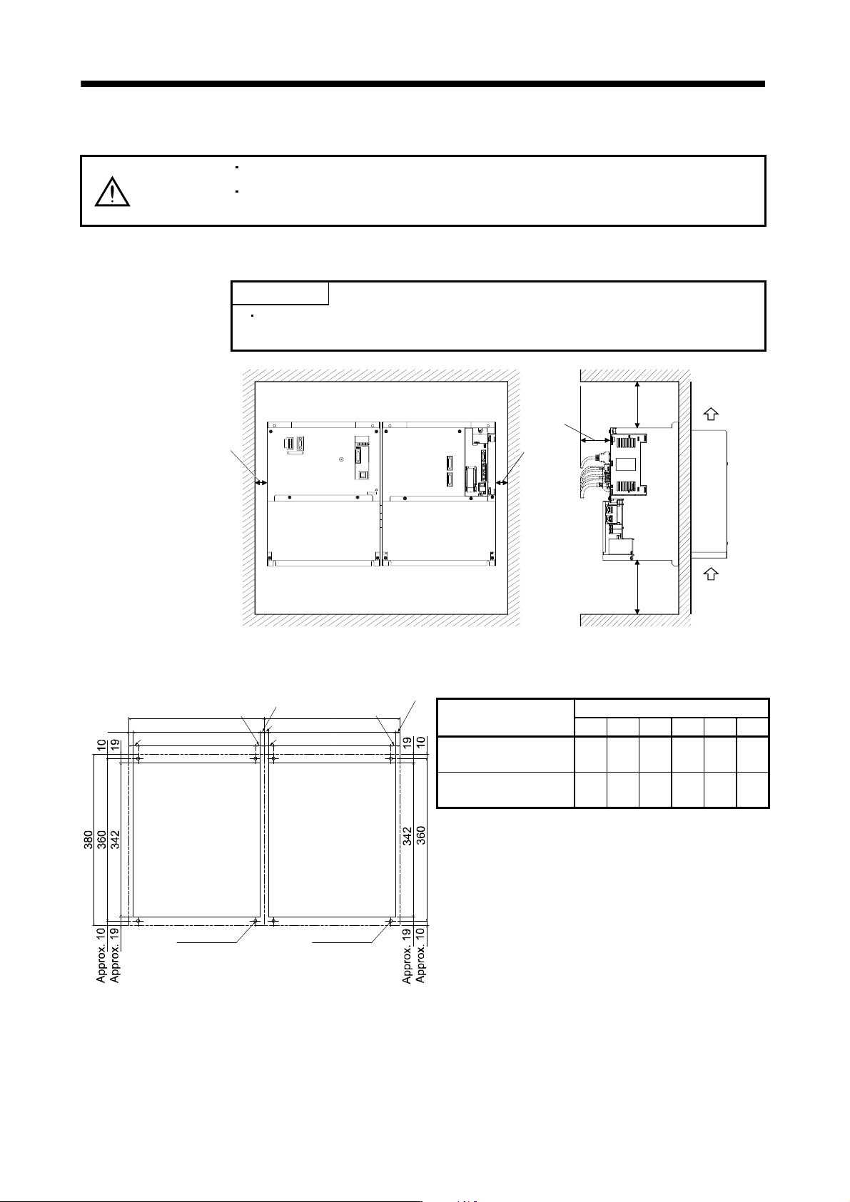
13.2.1 Installation direction and clearances
CAUTION
Install the equipment in the specified direction. Not doing so can cause a failure.
Leave the specified clearances between the converter unit/drive unit and the
control box inside walls or other equipment. Not doing so can cause a failure.
(1) Installation
POINT
Make sure to connect a drive unit to the right side of a converter unit as
shown in the diagram.
80mm or
more
Side view
Drive unitConverter unit
Front view
100mm or
more
120mm or more
30mm or
more
30mm or
more
Cooling fan
wind direction
Air
intake
(2) Mounting dimensional diagram
9.5
Converter unit
punched hole
Drive unit
punched hole
4-M6 screw
300
20
260
281
Approx. 9.5
Approx. 20
4-M6 screw
W1
W3
W2
W4
Approx. W5
Approx. W3
W5
[Unit: mm]
Drive unit model
Dimensions
W1 W2 W3 W4 W5 A
MR-J3-DU30KB, 37KB,
45KB4, 55KB4
300 260 20 281 9.5 M6
MR-J3-DU30KB4,
37KB4
240 120 60 222 9 M5
(3) Others
When using heat generating equipment such as the regenerative option, install them with full consideration
of heat generation so that the converter unit and drive unit is not affected.
Install the converter unit and drive unit on a perpendicular wall in the correct vertical direction.
13 - 22
13. SERVO AMPLIFIERS WITH A LARGE CAPACITY
(
30k TO 55kW
)
13.2.2 Inspection
WARNING
Before starting maintenance and/or inspection, turn off the power and wait for 20
minutes or more until the charge lamp turns off. Then, confirm that the voltage
between L
and L is safe with a voltage tester and others. Otherwise, an
electric shock may occur. In addition, always confirm from the front of the converter
unit whether the charge lamp is off or not.
CAUTION
Any person who is involved in inspection should be fully competent to do the work.
Otherwise, you may get an electric shock. For repair and parts replacement,
contact your safes representative.
POINT
Do not test the converter unit drive unit with a megger (measure insulation
resistance), or it may become faulty.
It is recommended to make the following checks periodically.
1) Check for loose terminal block screws. Retighten any loose screws.
2) Check the servo motor bearings, brake section, etc. for unusual noise.
3) Check the cables and the like for scratches and cracks. Perform periodic inspection according to operating
conditions.
4) Check the servo motor shaft and coupling for misalignment.
13 - 23
13. SERVO AMPLIFIERS WITH A LARGE CAPACITY
(
30k TO 55kW
)
13.3 Signals and wiring
WARNING
Any person who is involved in wiring should be fully competent to do the work.
Before wiring, turn off the power and wait for 20 minutes or more until the charge
lamp turns off. Then, confirm that the voltage between L
and L is safe with a
voltage tester and others. Otherwise, an electric shock may occur. In addition,
always confirm from the front of the converter unit whether the charge lamp is off
or not.
Ground the converter unit drive unit and the servo motor securely.
Do not attempt to wire the converter unit drive unit and servo motor until they
have been installed. Otherwise, you may get an electric shock.
The cables should not be damaged, stressed excessively, loaded heavily, or
pinched. Otherwise, you may get an electric shock.
CAUTION
Wire the equipment correctly and securely. Otherwise, the servo motor may
operate unexpectedly, resulting in injury.
Connect cables to correct terminals to prevent a burst, fault, etc.
Ensure that polarity ( , ) is correct. Otherwise, a burst, damage, etc. may occur.
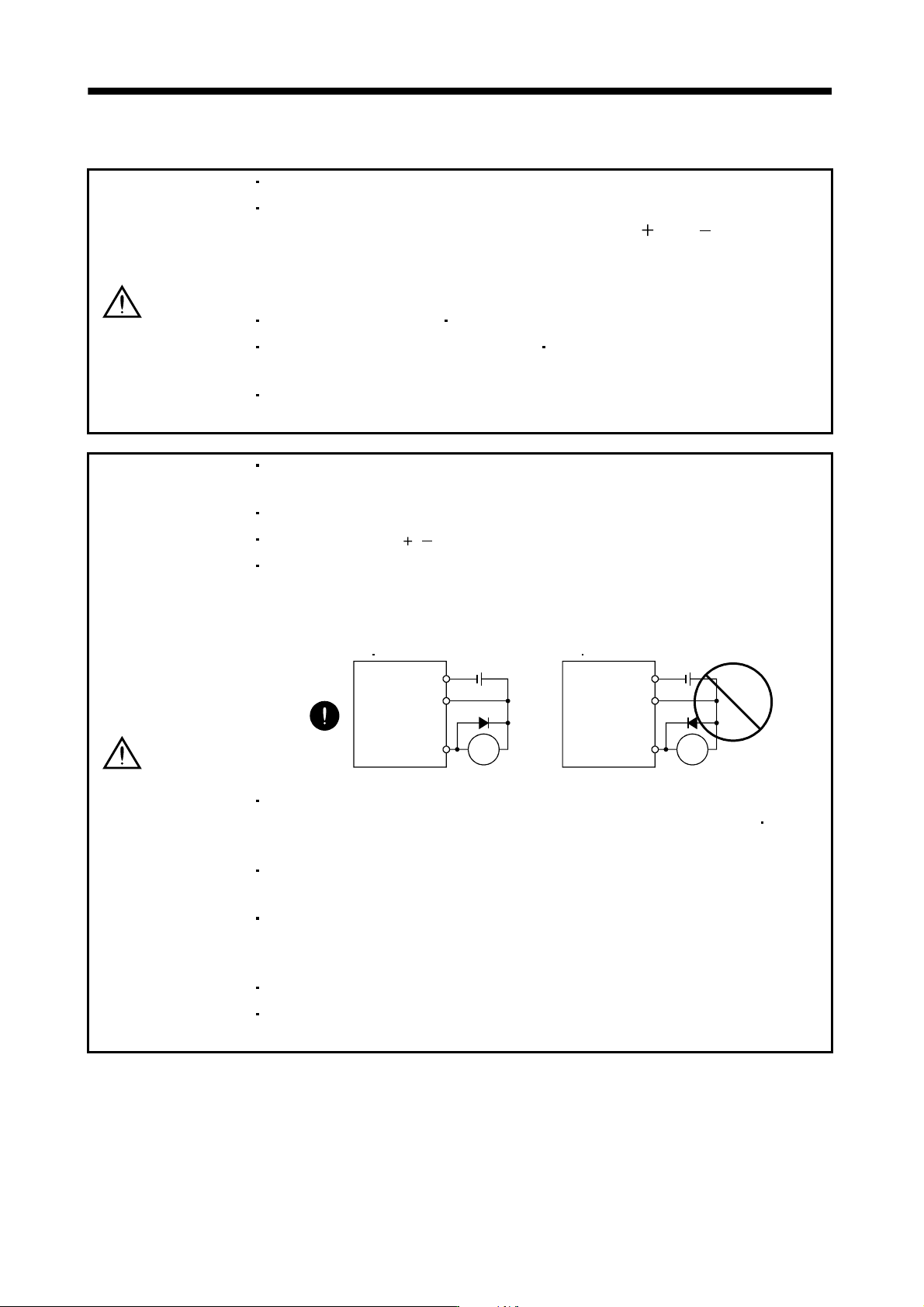
The surge absorbing diode installed to the DC relay designed for control output
should be fitted in the specified direction. Otherwise, the signal is not output due to
a fault, disabling the forced stop (EM1) and other protective circuits.
Converter unit
drive unit
RA
DOCOM
DICOM
Control
output
signal
24VDC
Converter unit
drive unit
Control
output
signal
RA
DOCOM
DICOM
24VDC
Use a noise filter, etc. to minimize the influence of electromagnetic interference,
which may be given to electronic equipment used near the converter unit
drive
unit.
Do not install a power capacitor, surge suppressor or radio noise filter (FR-BIF-(H)
option) with the power line of the servo motor.
When using the regenerative resistor, switch power off with the alarm signal.
Otherwise, a transistor fault or the like may overheat the regenerative resistor,
causing a fire.
Do not modify the equipment.
During power-on, do not open or close the motor power line. Otherwise, a
malfunction or faulty may occur.