sh030051g.pdf - 第250页
11 - 45 11. OPTIONS AND AUXILI ARY EQUIPMENT 11.4 Power regeneration converter POINT When using the FR-RC-(H) power regener ative converter, refer to "Power Regeneration Converter FR-RC Inst ruction Manual (IB(NA)66…
11 - 44
11. OPTIONS AND AUXILIARY EQUIPMENT
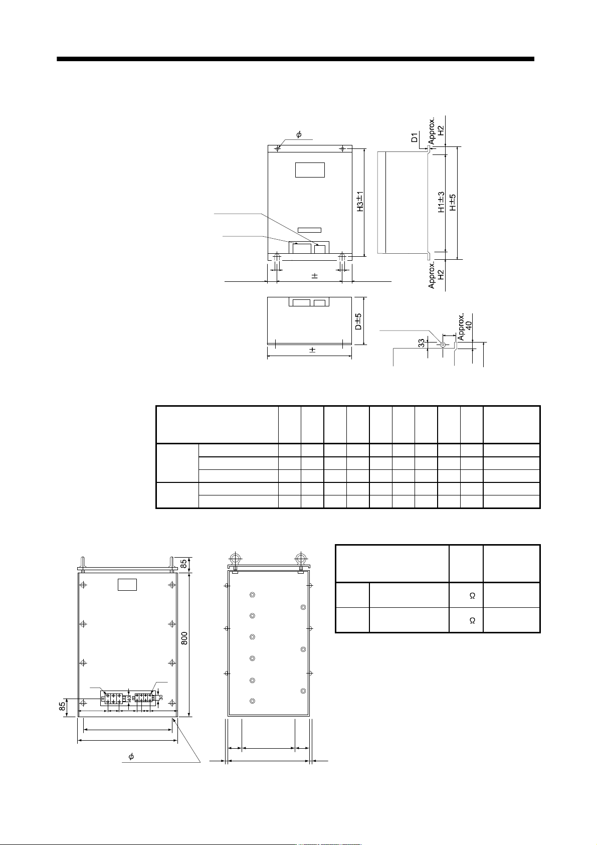
(2) FR-BR- (H) resistor unit
[Unit: mm]
2- C
Control circuit
terminal
Main circuit
terminal
W1 1
Approx. 35
Approx. 35
204
Hanging bolt
C
C
W 5
For FR-BR-55K/FR-BR-H55K, a hanging bolt
is placed on two locations (Indicated below).
(Note)
(Note)
Note. Ventilation ports are provided on both sides and the top. The bottom is open.
Resistor unit W W1 H H1 H2 H3 D D1 C
Approximate
mass
[kg]
200V
class
FR-BR-15K 170 100 450 410 20 432 220 3.2 6 15
FR-BR-30K 340 270 600 560 20 582 220 4 10 30
FR-BR-55K 480 410 700 620 40 670 450 3.2 12 70
400V
class
FR-BR-H30K 340 270 600 560 20 582 220 4 10 30
FR-BR-H55K 480 410 700 620 40 670 450 3.2 12 70
(3) MT-BR5- (H) resistor unit
[Unit: mm]
4 15 mounting hole
30075 75
4507.5 7.5
M6
M4
193
189
480
510
37 60 2110
NP
Resistor unit
Resistance
value
Approximate
mass
[kg]
200V
class
MT-BR5-55K 2.0
50
400V
class
MT-BR5-H75K 6.5
70
11 - 45
11. OPTIONS AND AUXILIARY EQUIPMENT
11.4 Power regeneration converter
POINT
When using the FR-RC-(H) power regenerative converter, refer to "Power
Regeneration Converter FR-RC Instruction Manual (IB(NA)66330)".
When using the power regeneration converter, set "
01" in parameter No.PA02.
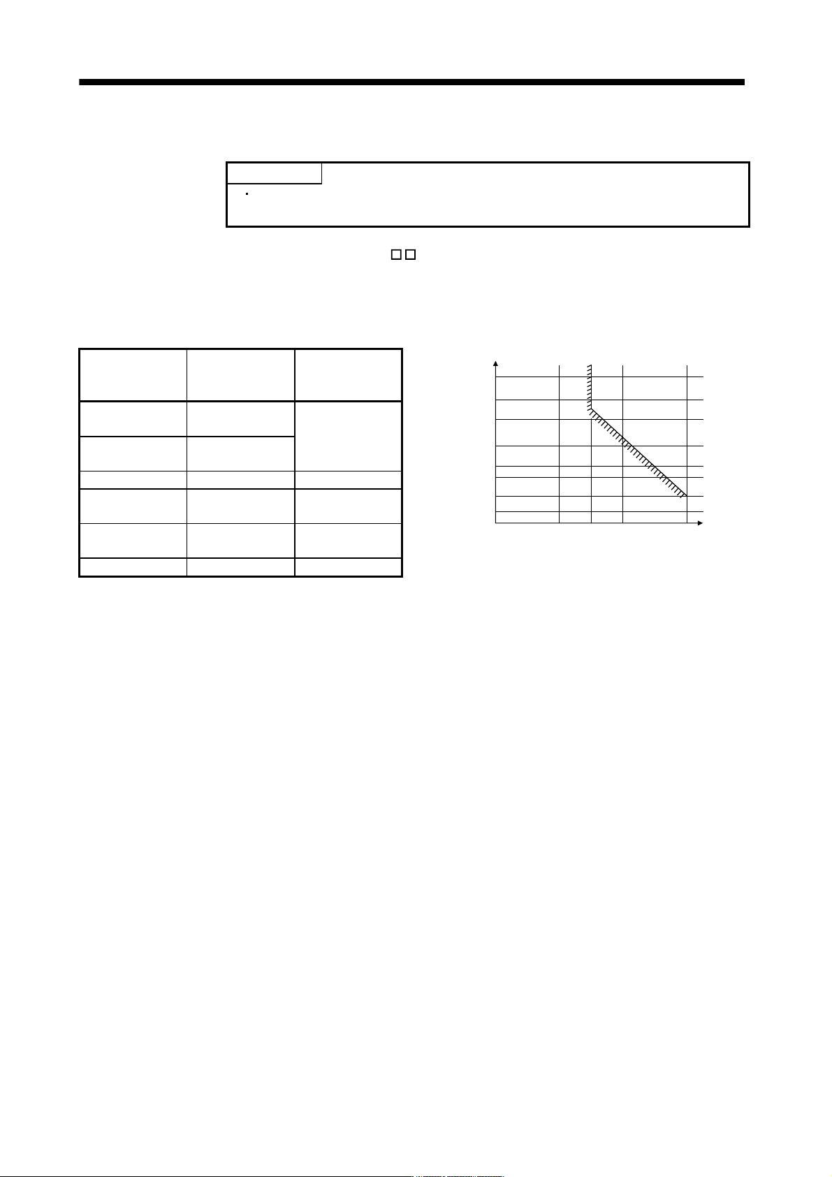
(1) Selection
The converters can continuously return 75% of the nominal regenerative power. They are applied to the
servo amplifiers of the 5k to 22kW.
Power regeneration
converter
Nominal
regenerative power
(kW)
Servo amplifier
050
75
100 150
500
300
200
100
50
30
20
Continuous energization time [sec]
Nominal regenerative power (%)
FR-RC-15K 15
MR-J3-500B
MR-J3-700B
FR-RC-30K 30
MR-J3-11KB
MR-J3-15KB
FR-RC-55K 55 MR-J3-22KB
FR-RC-H15K 15
MR-J3-500B4
MR-J3-700B4
FR-RC-H30K 30
MR-J3-11KB4
MR-J3-15KB4
FR-RC-H55K 55 MR-J3-22KB4
11 - 46
11. OPTIONS AND AUXILIARY EQUIPMENT
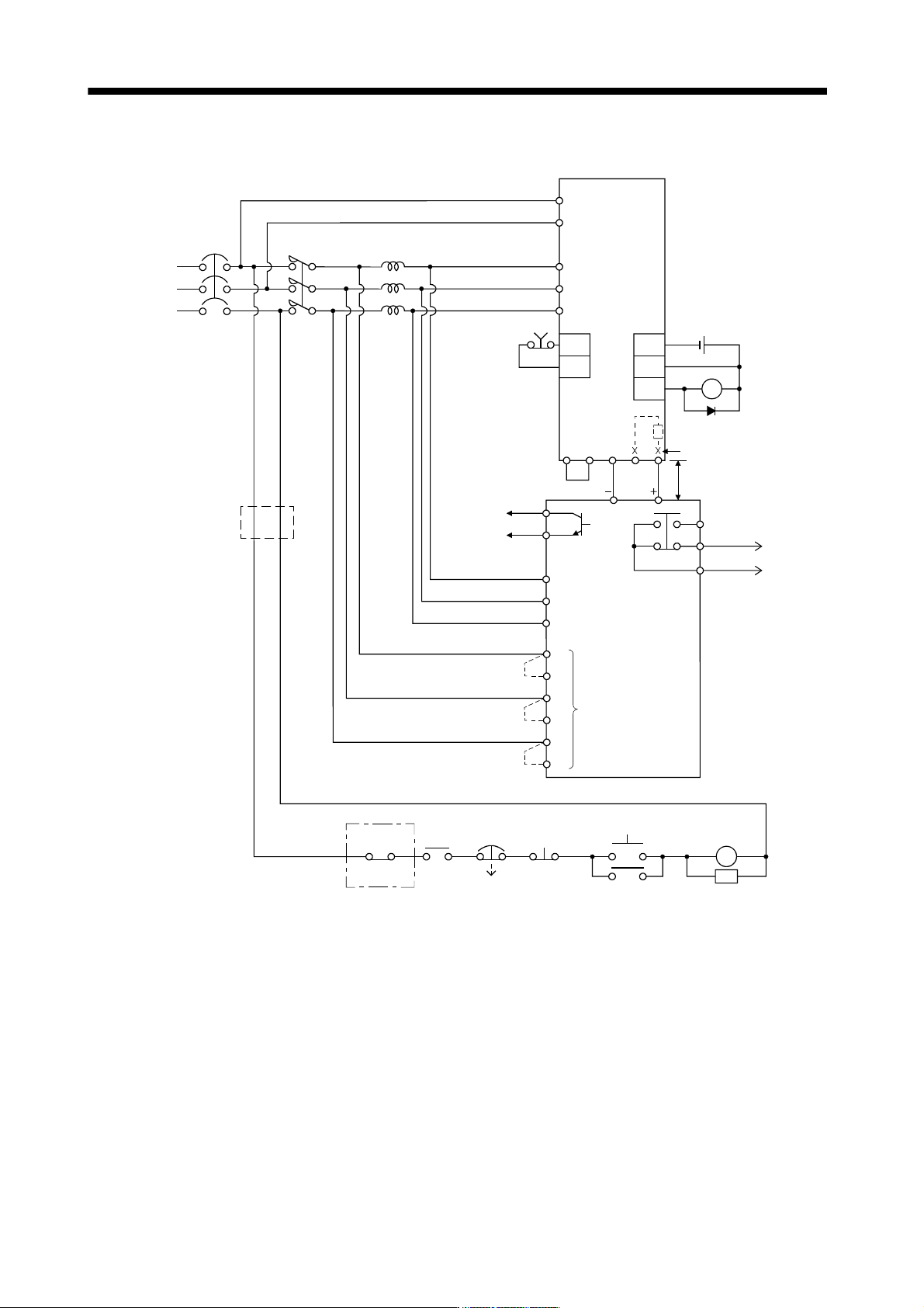
(2) Connection example
NFB
MC
Servo amplifier
L
11
L21
L1
L
2
L3
SK
ON
MC
BC
NPC
RDY
SE
Alarm
output
RDY
output
A
B
C
5m or less
Operation ready
MC
OFF
EMG
ALM
RA2
FR-RC-(H)
Ready
Power factor improving reactor
(Note 7)
R/L
1
S/L2
T/L
3
B
C
RRX
R
SX
S
TX
T
Phase detection
terminals
(Note 1)
Power regeneration
converter FR-RC-(H)
N/
P/
EM1
RA
DOCOM
DICOM
ALM Trouble
(Note 3)
DOCOM
Forced stop
24VDC
P2P1
(Note 4)
(Note 2)
CN3 CN3
(Note 5)
(Note 6)
Power supply
Note 1. When not using the phase detection terminals, fit the jumpers across RX-R, SX-S and TX-T. If the jumpers remain
removed, the FR-RC-(H) will not operate.
2. When using servo amplifiers of 5kW and 7kW, always remove the lead of built-in regenerative resistor connected
to P terminal and C terminal.
3. When setting not to output Trouble (ALM) with parameter change, configure power supply circuit for turning
magnetic contactor off after detecting an occurrence of alarm on the controller side.
4. Between P
1
and P
2
(P
1
and P for 11kW to 22kW) is connected by default.
5. Stepdown transformer is required for coil voltage of magnetic contactor more than 200V class in 400V class servo
amplifiers.
6. Refer to section 1.3 for the power supply specification.
7. For selection of power factor improving AC reactors, refer to "Power Regeneration Converter FR-RC Instruction Manual
(IB(NA)66330)".